6.18 PC/104 ISA Bus (J1, J2)
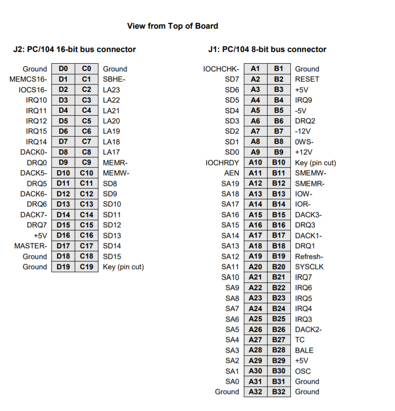
The PC/104 bus is essentially identical to the ISA Bus except for the physical design. It specifies two pin and socket connectors for the bus signals. A 64-pin header J1 incorporates the 62-pin 8-bit bus connector signals, and a 40-pin header J2 incorporates the 36-pin 16-bit bus connector signals. The additional pins on the PC/104 connectors are used as ground or key pins. The female sockets on the top of the board enable stacking another PC/104 board on top of the board, while the male pins on the bottom enable the board to plug into another board below it.
In the pinout figures below, the tops correspond to the left edge of the connector when the board is viewed from the primary side (side with the CPU chip and the female end of the PC/104 connector) and the board is oriented so that the PC/104 connectors are along the bottom edge of the board.
Last updated