6. CONNECTOR LOCATIONS
This page describes the connector locations on the Floyd SC carrier card.
6.1 Main Component Locations
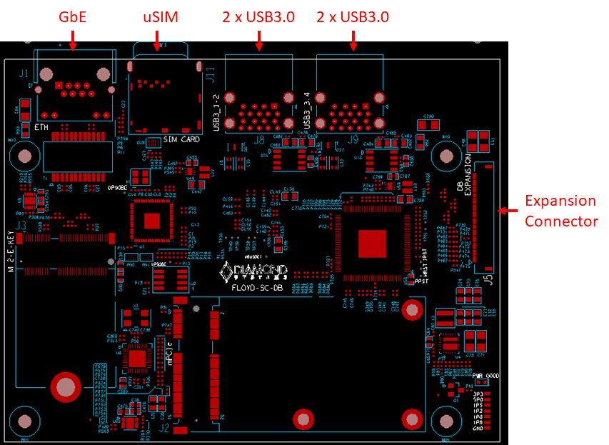
Following figure depicts the top callout view of the Floyd SC carrier board indicating the component locations.
6.2 IO Connectors and LED specification
The following table lists the I/O connectors and their corresponding functions.
Connector | Function |
J1 | GbE |
J5 | Expansion Connector |
J8 | 2 x USB 3.0 |
J9 | 2 x USB 3.0 |
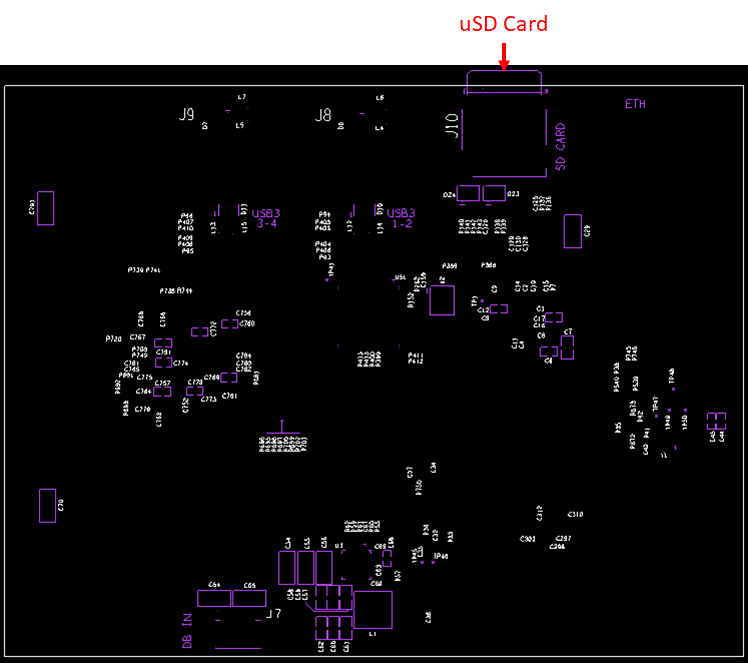
J10 | uSD card |
J11 | uSIM |
The following table list the LED and its corresponding functions.
Connector | Function |
D26 | GbE |
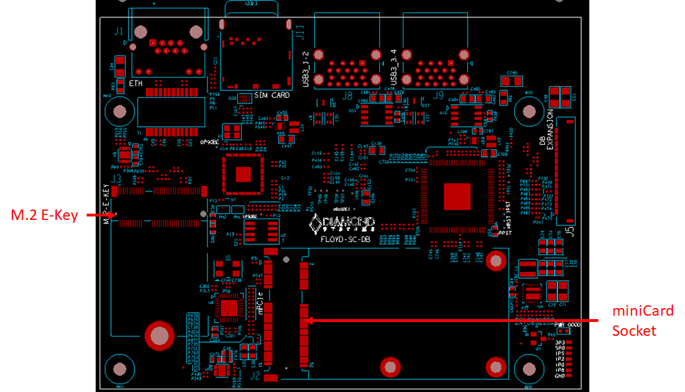
7.4 Expansion Slot Locations
The following table lists the I/O connectors and their corresponding functions.
Connector | Function |
J2 | miniCard socket |
J3 | M.2 E-Key |
Last updated