6.8 Page 4: dsPIC Interface
This is an enhanced features page. It is inaccessible unless enhanced features are enabled.
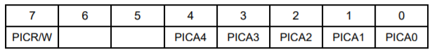
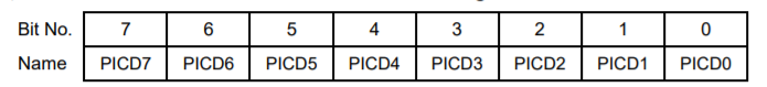
Page 4, Base + 12 Read/Write dsPIC Data Register
PICR/W | Read/write control: 0 = write, 1 = read |
PICA4-0 | dsPIC internal address |
Writing a byte with R/W = ‘0’ will cause the dsPIC to write the data contained in the dsPIC Data Register above to the dsPIC internal address indicated by PICA4-0. Writing a byte with R/W = ‘1’ will cause the dsPIC to read the data at dsPIC internal address, PICA4-0 and place the received data in the dsPIC Data Register.
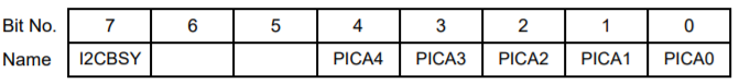
Page 4, Base + 13 Read dsPIC status register
I2CBSY | I2C port status bit: |
0 | Last I2C operation completed |
1 | Last I2C operation in progress |
PICA4-0 | dsPIC address last accessed |
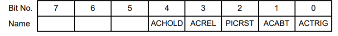
Page 4, Base + 14 Write Auto-Autocalibration Command Register
Only one bit can be set to ‘1’ at once. Bits are processed MSB to LSB. The first ‘1’ determines which command is carried out.
ACHOLD | 1 = Auto-autocal process is disabled. Autocalibration must be triggered by software |
ACREL | 1 = Auto-autocal process is enabled. Auto-autocalibration will occur whenever the board requires it. |
PICRST | 1 = Reset dsPIC device. This command is normally not needed. |
ACABT | 1 = Abort any currently running auto-autocal operation immediately |
ACTRIG | 1 = Initiate an auto-autocal process immediately |
Page 4, Base + 14 Read Auto-Autocalibration Status Register
ACHOLD | 1 = dsPIC in holdoff mode (auto-autocal disabled) |
PICPRST | 1 = dsPIC device present on board |
ACERR | 1 = dsPIC detected errors during last Auto-autocal process |
ACACT | 1 = Auto-autocal process currently in progress |
PICBSY | 1 = dsPIC busy, either with auto-autocal or some other activity |
Details concerning auto-autocalibration can be found at in chapter 15 on page 48.
Page 4, Base + 15 Write dsPIC Programming Register
This register is used to control the on-board dsPIC microcontroller. The dsPIC controls the auto-autocalibration process, and it also provides the communication link between the board and its serial port. The bits in this register are control bits, not register bits. Only one bit can be set to ‘1’ at once. Bits are processed MSB to LSB. The first ‘1’ determines which command is carried out
PSTART | Drive EN_PROG# signal low. |
PSTOP | Drive EN_PROG# high. |
PGDOUT | FPGA makes PIC_PGD line an output, but leave at current level (i.e. perform input to find current level, set line as an output at same level.) |
PGDIN | FPGA makes PIC_PGD line an input. |
PGDW1 | If PIC_PGD line is in output mode, set high |
PGDW0 | If PIC_PGD line is in output mode, set low |
PGCW1 | Set PIC_PGC line high |
PGCW0 | Set PIC_PGC line low |
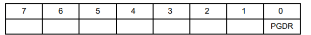
Page 4, Base + 15 Read dsPIC Programming Register
PGDR Reads back current level of PIC_PGD line (low = 0, high = 1)
Last updated