8. IO CONNECTORS
This page describes the pinouts of various connectors available with the Floyd SC carrier card.
8.1 Power IN(J2)
The carrier board provides a barrel connector for main input power. The connector has a 2.5mm center pin and is intended for use with mating connectors with 2.5mm inner diameter and 5.5mm outer diameter.
Input voltage = +12V to +24V
The connections for the power input connector are Tip = +V and Ring = -V.
Connector Part Number: PJ-202BH
8.2 RTC Battery(J18)
The external battery input is intended for a 3V battery.
The pinouts for the RTC Battery connector are specified below.
Connector Part No.: 0022035025
DSC Mating part No.: 6980524
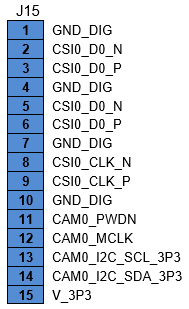
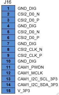
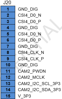
8.3 Camera (J15,J16,J20)
The carrier board embeds three identical 15-pin connectors for multiple CSI Camera connectivity. Ribbon cables are used to directly plug the camera modules.
Pinout is as specified below:
Connector Part No: 1-84952-5
Camera supported: Raspberry Pi Camera Board v2 - 8 Megapixels
Mating cable: FFC Cable included with the camera
8.4 Controlled Area Network (J14)
Floyd SC model FLD-SCBB-02 implements one CAN bus controller port when integrated with Jertson Xavier NX module.
Connector Part No: BM04B-GHS-TBT
Mating cable: 6981182
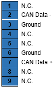
The CAN cable 6981182 has the near end terminated with the mating connector GHR-04V-S & the far end with a DB9M. When the cable is used to access the CAN port, the DB9M follows the pinouts as shown below:
8.5 Ethernet Connectors (J3,J4)
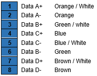
The ethernet ports are terminated on standard RJ45 connectors that has integrated LEDs. The connectors follows standard TIA/EIA 568B pinout.
Connector Part No: LPJG101AGNL-1
Mating cable: Standard LAN Cat6 cable
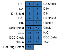
8.6 HDMI Connector (J6)
HDMI port is terminated on a standard vertical connector. Connector follows standard HDMI pinout.
Connector Part No: QJ3119C-WFB1-4F
Mating cable: Standard HDMI cable
8.7 DP Connector (J8)
DP port is terminated on a standard vertical connector. Connector follows standard DP pinout.
Connector Part No: 3VD21203-H7U0-4H
Mating cable: Standard DP cable
8.8 USB2.0 Connector (J5)
The carrier board hosts two USB 2.0 ports accessible on a vertically stacked standard USB 2.0 Type A socket that uses standard pinout.
Connector Part No: UB1112C-8FDH-4F
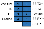
8.9 USB3.0 Connector (J7)
The carrier board hosts one USB 3.0 ports accessible on a upright standard USB 3.0 socket that uses standard pinout.
Connector Part No: UEA3119C-4EB1-4H
8.10 M.2 PCIe Connector (J19)
The Floyd carrier board is equipped with an M.2 PCIe SSD M-keyed connector for 2280 0r 2242 sized modules for storage applications. An M.2 SSD is "keyed" to prevent the insertion of a card connector to an incompatible socket on the board.
x4 PCIe lane available from module is routed directly to M.2 PCIe connector.
Connector Part Number/Type: 10128798-001RLF
Connector Key: M-Key
Add-on Module: M.2 2280 SSD (W 22 mm x L 80 mm), M.2 2242 SSD (W 22 mm x L 42 mm)
8.11 Daughter Board Expansion (J9)
The Floyd SC carrier supports additional interfaces using expansion connector for an optional daughter card. Pinout of Expansion connector is as below:
Connector Part Number/Type: FH55-40S-0.5SH, 40 position highspeed FPC connector
8.12 Serial connector(J13)
Two serial ports are connected to one single 2x5 2mm header. One half of this connector has 1st Serial port which is RS232 protocol and second half has 2nd Serial port which is either RS232 or RS485 based on Jumper settings. Pinout is as follows.
Connector Part No: 2011-2X40G00SD, 2x5 2mm Header
Mating cable: 6981075
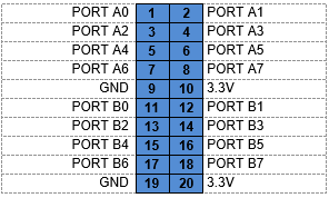
8.13 Digital I/O (J11)
The board provides 16x GPIOs which can be individually programmed for input or output functionalities. The GPIOs are accessible on a 2x10 2.54 mm header.
The pinouts of the connector is as given below:
Connector Part No: 2x10 2.54 mm Header
Mating cable: C-DB9M-2
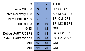
8.14 Utility Connector
The carrier board provides access to utility signals on a 2x10 header.
The pinouts for the utility connector are specified below.
Connector Part No: 220-97-36GB01
Connector type: 2x10, 2 mm Header
8.15 FAN Connector
The pinouts for the fan connector are specified below.
Connector Part Number: 0533980471-2
Supported Fan Model: Delta ASB0305HP-00CP4
Last updated
