10. CONNECTOR PINOUT SPECIFICATION
Illustrates the pinouts of all connectors available on Gemini carrier
Note: Signals highlighted by grey are not supported on Gemini.
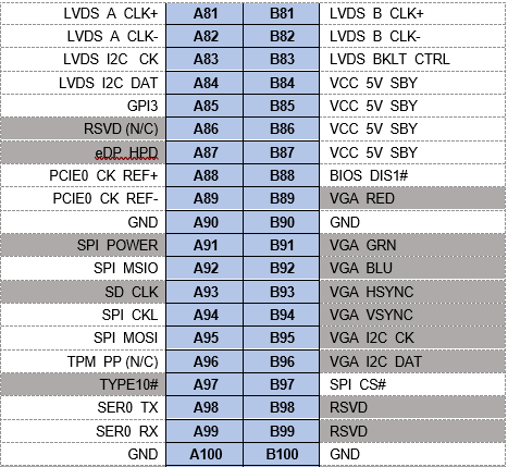
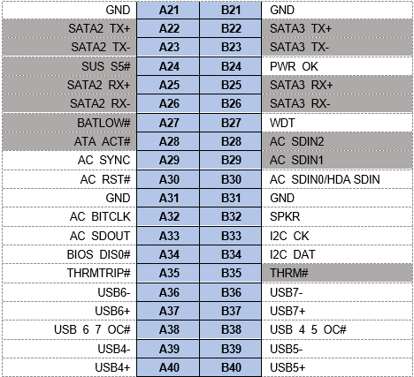
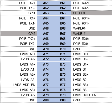
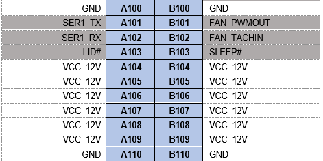
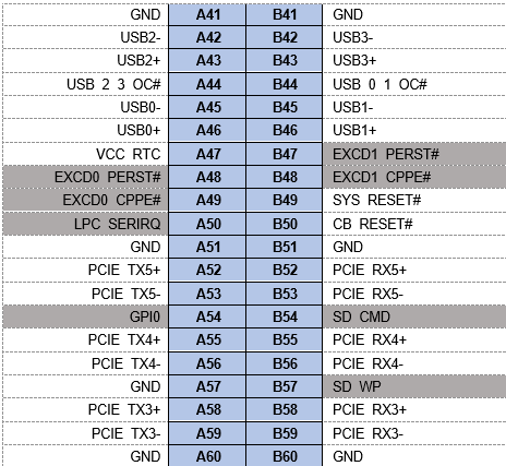
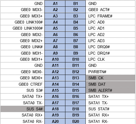
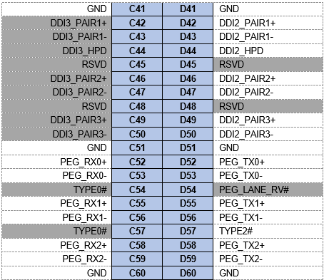
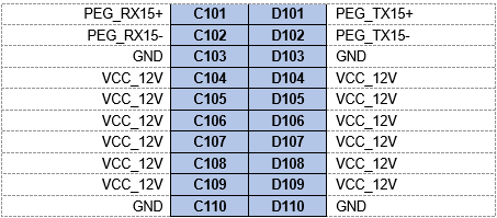
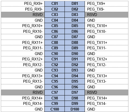
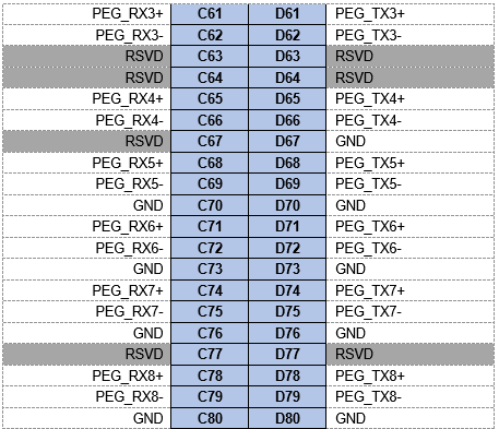
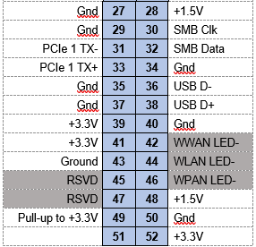
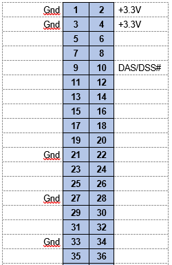
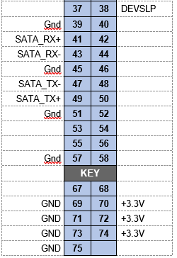
10.1 J5, J8 COM Express Type 6 connector
COM Express type 6 row A and B pinout:
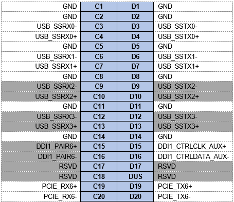
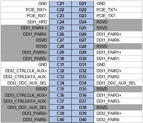
COM Express type 6 row C and D pinout:
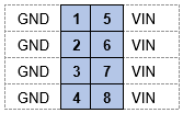
10.2 J25 Power IN Connector
Connector Part Number : ASP-194529-01
Mating cable part no: DSC No.6980512
Mating connector part no.: IPD1-04-D-K
Crimp terminal part no.: CC79L-2024-01-L/CC79R-2024-01-L
10.3 J26 External Battery Connector
Connector part no. : Molex Mini-SPOX 22057025
Mating cable Part no. : DSC No. 6980524
Mating connector part no.: 5037-5023/A2505H02-2P
Crimp terminal part no.: 0870-1039/A2505TOP-2
10.4 J21, J22 Ethernet Connectors
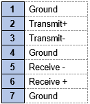
10.4.1 J21 Ethernet connector
Connector Part No. : FCI 98414-F06-10ULF
Mating cable part No. : DSC No. 6980604
Mating connector part no.: 10073599-010LF
Crimp terminal part no.: 77138-001LF
10.4.2 J22 Ethernet connector
Connector Part No. : FCI 98414-F06-10ULF
Mating cable part No. : DSC No. 6980604
Mating connector part no.: 10073599-010LF
Crimp terminal part no.: 77138-001LF
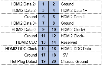
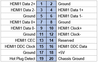
10.5 J27, J29 HDMI Connectors
10.5.1 J27 HDMI connector
Connector Part No. : FCI 98414-F06-20ULF
Mating cable part No. : DSC No. 6980605
Mating connector part no.: 10073599-010LF
Crimp terminal part no.: 77138-001LF
10.5.2 J29 HDMI connector
Connector Part No. : FCI 98414-F06-20ULF
Mating cable part No. : DSC No. 6980605
Mating connector part no.: 10073599-010LF
Crimp terminal part no.: 77138-001LF
10.6 J32 LVDS LCD Connector
Connector Part No. : Molex 5015713007
Mating cable part No. : Specific to the target display
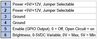
10.7 J12 LCD Backlight Connector
Connector Part No. : Molex 53261-0671
Mating cable part No. : Specific to the target display
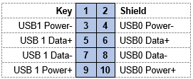
10.8 J16, J17 USB 2.0 Connectors
10.8.1 J16 USB2.0 connector
Connector Part No. : FCI 98414-F06-10ULF
Mating cable part No. : DSC No. 6980602
Mating connector part no.: 10073599-010LF
Crimp terminal part no.: 77138-001LF
10.8.1 J17 USB2.0 connector
Connector Part No. : FCI 98414-F06-10ULF
Mating cable part No. : DSC No. 6980602
Mating connector part no.: 10073599-010LF
Crimp terminal part no.: 77138-001LF
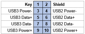
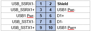
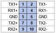
10.9 J14, J15 USB 3.0 connectors
10.9.1 J14 USB3.0 connectors
Connector Part No. : FCI 98414-F06-10ULF
Mating cable part No. : DSC No. 6980603
Mating connector part no.: 10073599-010LF
Crimp terminal part no.: 77138-001LF
10.9.2 J14 USB3.0 connectors
Connector Part No. : FCI 98414-F06-10ULF
Mating cable part No. : DSC No. 6980603
Mating connector part no.: 10073599-010LF
Crimp terminal part no.: 77138-001LF
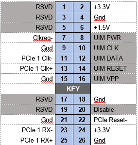
10.10 J18 PCIe miniCard Socket
Connector Part No. : MM60-52B1-E1-R650
10.11 J19 M.2 SATA SSD Socket
Connector Part No. : MDT320M030001
10.12 J20 SATA Connector
Mating cable part No. : DSC No. 6989101
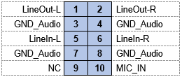
10.13 J23 Audio Connector
Connector Part No. : FCI 98414-F06-10ULF
Mating cable part No. : DSC No. 6980608
Mating connector part no.: 10073599-010LF
Crimp terminal part no.: 77138-001LF
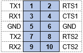
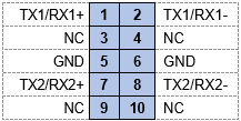
10.14 J3, J4 Serial port Connectors
10.14.1 J3 Serial port connector
RS232 pinout:
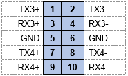
RS422 pinout:
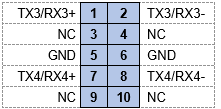
RS485 pinout:
Connector Part No. : FCI 98414-F06-10ULF
Mating cable part No. : DSC No. 6980601
Mating connector part no.: 10073599-010LF
Crimp terminal part no.: 77138-001LF
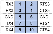
10.14.2 J4 Serial port connector
RS232 pinout:
RS422 pinout:
RS485 pinout:
Connector Part No. : FCI 98414-F06-10ULF
Mating cable part No. : DSC No. 6980601
Mating connector part no.: 10073599-010LF
Crimp terminal part no.: 77138-001LF
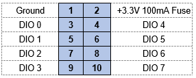
10.15 J33 Digital I/O
Connector Part No. : FCI 98414-F06-10ULF
Mating cable part No. : DSC No. 6980609
Mating connector part no.: 10073599-010LF
Crimp terminal part no.: 77138-001LF
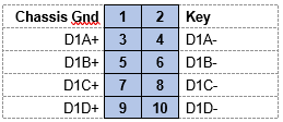
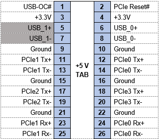
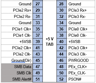
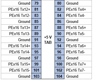
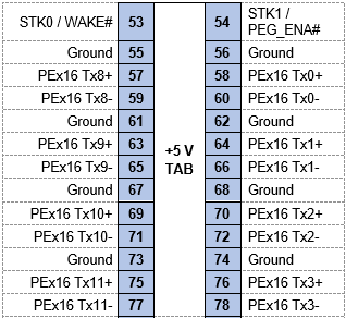
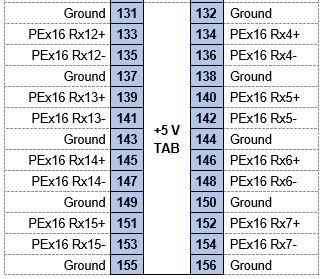
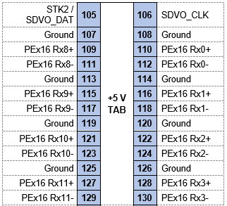
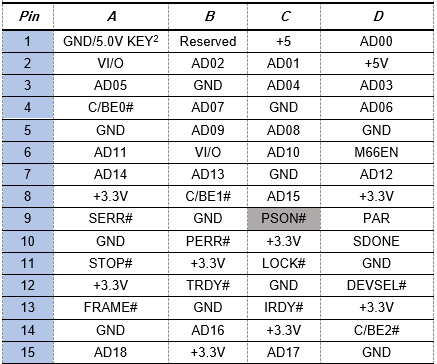
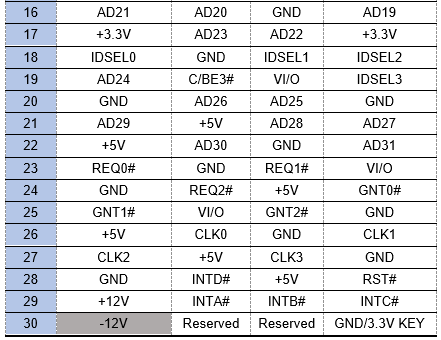
10.16 J1 PCIe/104 Connector
Bank 1 pinout:
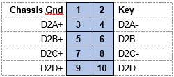
Bank 2 Pinout
Bank 3 pinout
10.17 J2 PCI-104 Connector
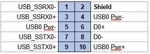
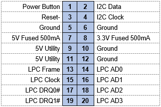
10.18 J7 Utility Connector
Connector Part No. : 10112690-G03-10ULF
Mating cable part No. : DSC No. C-20MM-18
Mating connector part no.: 10073599-010LF
Crimp terminal part no.: 77138-001LF
Last updated