12. JUMPER DESCRIPTION
This page describes the jumper block functionalities provided by the Athena IV baseboard.
12.1 Serial Port & DIO pull-up/pull-down Configuration [JP1]
The 2x6 2mm jumper JP1 is used to:
Select the protocol for the serial ports
Enable the pull-up or pull-down on the DIOs
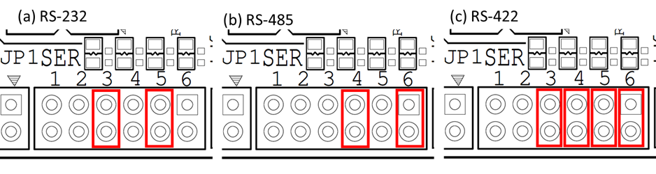
12.1.1 Select the protocol for the serial ports
The serial port protocol mode selection is as tabulated below:
By default, the serial ports' outputs are disabled to prevent any accidental damages to the port pair.
The protocol selection remains same for serial ports 1 & 2 and serial ports 3 &4 ie inserting a jumper on location 5 on JP1 configures the both serial ports 1 & 2 in RS-232 mode
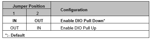
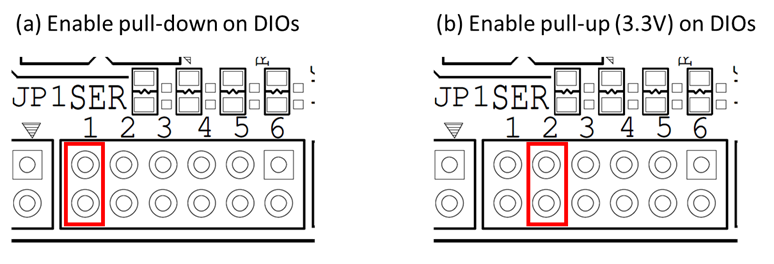
12.1.2 Enable the pull-up or pull-down on the DIOs
The on-boards DIOs can be pulled up or down with the help of jumper JP1.The configurations are as tabulated below:
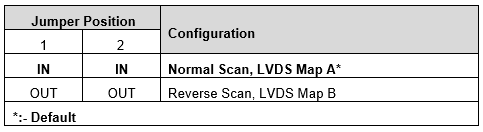
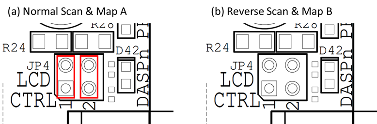
12.2 LVDS Scan & Mapping [JP4]
The 2x2 2mm jumper JP4 is used to set the scan direction & mapping for certain LVDS displays. The configurations are as tabulated below:
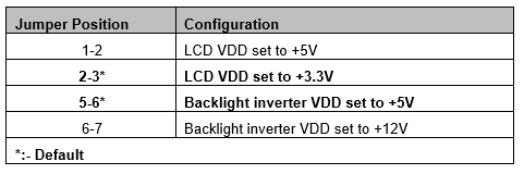
12.3 LVDS LCD Panel Voltage Select [JP5]
The 1x7 2.54mm jumper JP5 is used to configure the LVDS LCD panel voltages. The configurations are as tabulated below:
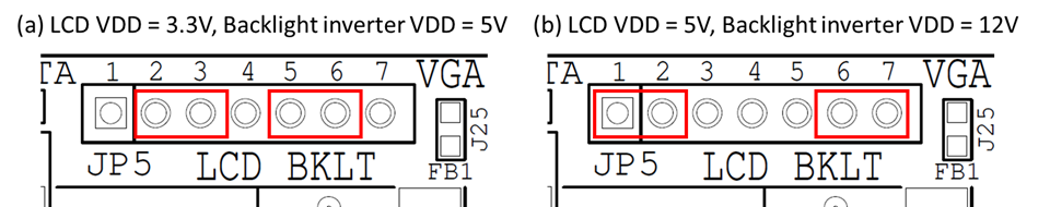
12.4 ISA Base Address [JP6]
A part of 2x9 2mm jumper JP6 is used to configure the base address of the A/D circuit. The configurations are tabulated below:
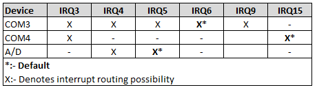
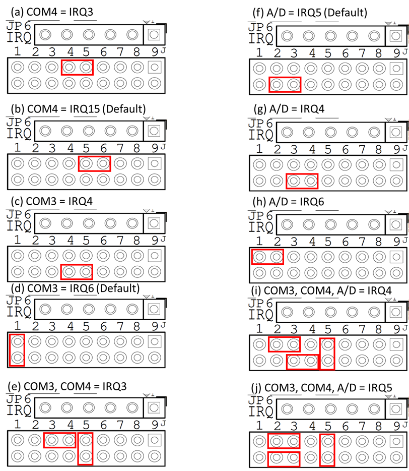
12.5 ISA IRQ [JP6]
A part of 2x9 2mm jumper JP6 is used to configure the IRQ for the serial COM ports & A/D IRQ. The configurations are as tabulated below:
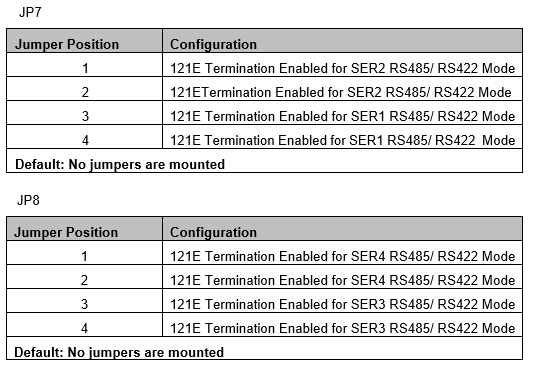
12.6 Termination Enable for Serial Ports [JP7, JP8]
The two 2x5 2mm jumpers JP7 & JP8 are used to enable the 121E termination for the serial ports in RS-422 & RS-485 protocol modes. To enable the 121E termination for RS-422 & RS-485 modes, appropriate jumpers are mounted. The jumpers are removed to disable the 121E termination for RS-232 mode. The configurations are as tabulated below:
In RS-232, make sure to remove all the jumpers as the serial ports might end up failing due to the 121E termination on the communication lines
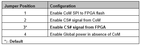
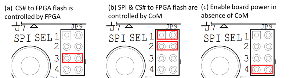
12.7 SPI Select [JP9]
The 2x3 2mm jumper JP9 is used to configure the SPI lines to the FPGA SPI flash & enable the board power in absence of CoM. The configurations are as tabulated below:
Jumper on JP9 location 4 should never be mounted in presence of CoM. Mounting like this may damage the CoM
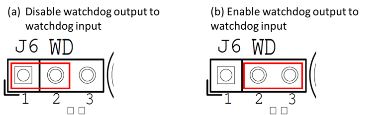
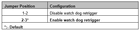
12.8 Watchdog Timer [J6]
The 1x3 2.54mm jumper is used to configure the system watchdog. The configurations are as tabulated below:
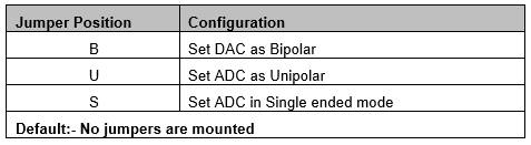
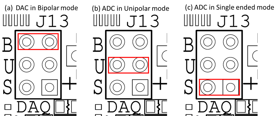
12.9 DAQ Configuration [J13]
The 2x3 2mm jumper J13 is used to set the configuration for the DAQ unit. The configurations are as tabulated below:
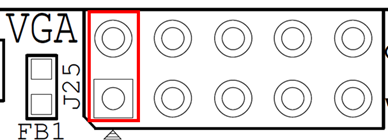
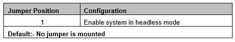
12.10 Headless Mode [J25]
The 2x5 2.54 header connector J25 for VGA is partly used to enable the system in headless mode.
Last updated