15. SYSTEM ASSEMBLY
Describes how to assemble/disassemble the Gemini Carrier card assembly
Always observe ESD safe handling procedures to minimize any risk of damages to the system
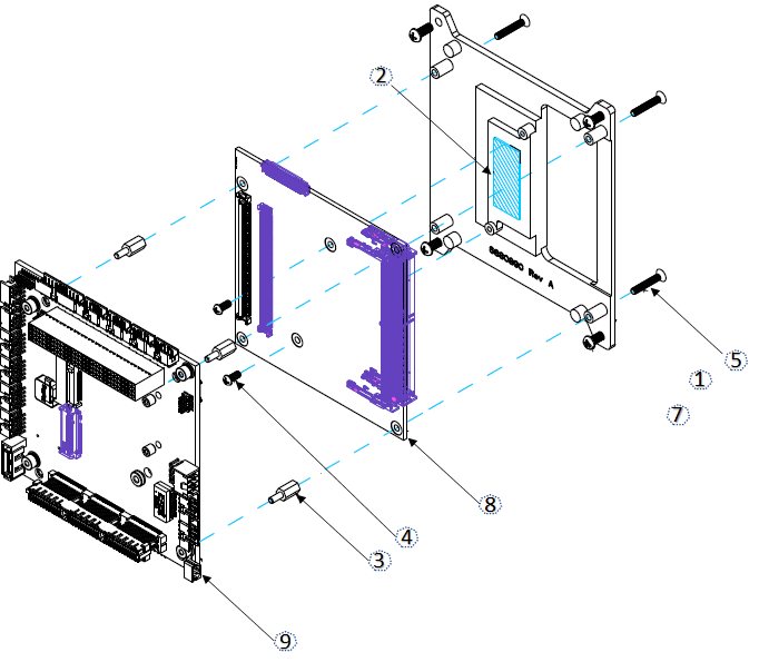
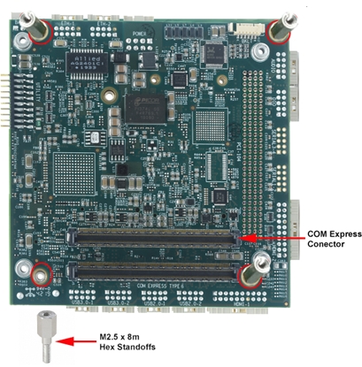
1. Place the Gemini carrier board on an antistatic surface on the front side with the COM Express connector facing above.
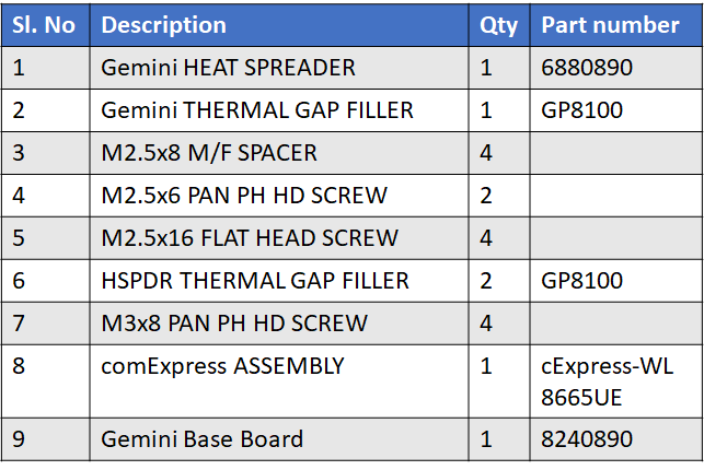
2. Mount four M2.5 x 8mm male-female standoffs into the mounting holes on the carrier boards as marked in image below.
3. Align the comExpress module connector to the comExpress connector to align both connectors. Ensure that required memory modules are plugged onto the SODIMM socket.
4. Press firmly to interconnect both connectors.
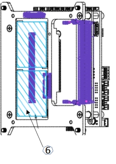
5. Inspect the heatspreader and ensure that the thermal pads are in good condition.
6. Remove all thermal pad liners from bottom of the heatspreader to avoid contaminating exposed thermal pad surfaces. Check orientation of heatspreader with respect to COM module before placing the heatspreader to avoid damaging thermal pads
Check orientation of heatspreader with respect to COM module before placing the heatspreader to avoid damaging thermal pads.
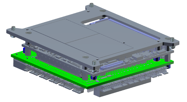
8. Install the heatspreader on top of the module.
9. Install 4 M2.5 x 16mm flat-head screws on the monting holes on top of the heat spreader.
Heat sink installation can be done either by securing the heatsink from bottom or from the top based on heatsink design. Heatspreader supports both options
Last updated