19.GENERATING AN ANALOG OUTPUT
There are 5 steps involved in performing a D/A conversion, or generating an analog output. Each step is described in more detail below. These instructions describe the necessary steps. The examples provided use direct programming instead of Universal Driver software for illustration. For instructions on generating an analog output using the Universal Driver, refer to the software user manual.
Set simultaneous update mode and/or DAC resolution if needed.
Configure the desired output range.
Compute the D/A code for the desired output voltage.
Write the value to the selected output channel.
Update the D/A
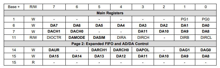
DA7-0 | D/A data bits 7-0 for both 12-bit and 16-bit modes. DA0 is the LSB |
DA11-0 | (in base+7) D/A data bits 11-8 for 12-bit mode only; DA11 is the MSB |
DA15–8 | (in page 2 base+15) D/A data bits 15 – 8 for 16-bit mode only; DA15 is the MSB |
DACH1-0 | D/A channel to receive current data in DA11-0 or DA15-0 |
DAMODE | 16/12-bit DAC mode. This bit should only be set for custom models of Helios with a 16-bit DAC |
DASIM | D/A simultaneous mode: 0 = immediate update with new data, 1 = simultaneous mode |
DAUR | D/A unique range: 1 = set selected channel to given range, 0 = set all channels to same range |
DARCH1-0 | D/A channel to configure for given range when DAUR = 1 |
DAPOL | D/A polarity setting: 0 = unipolar, 1 = bipolar |
DAG1-0 | D/A gain setting |
DACBSY | Indicates the DAC is busy updating (approx. 4 µS). 1 = Busy, 0 = Idle. Any writes to the DAC (registers 6 and 7 of page 0 or register 15 of page 2) while DACBSY = 1 will be ignored. |
Last updated