14.4.4 Page 2 Expanded FIFO and AD/DA Control
Page 2 Base + 12 Read/Write Expanded FIFO Control
EXFIFO | Expanded FIFO enable. Default and reset value is 0. 0 The FIFO is set in basic mode and the registers at base+5 and base+6 are in basic mode. The FIFO size is set to 48 samples and the threshold is set to 24. 1 The FIFO is set in enhanced mode, and the registers at base+5 and base+6 are in enhanced mode. The FIFO size is set to 2048 samples and the threshold is set to 1024. |
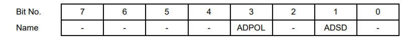
Page 2 Base + 13 Read/Write AD Mode Configuration
This register functions as an AD configuration jumper override for the DAQ subsection. This register resets to zero on power-up or reset.
ADPOL | A/D polarity configuration: 0 Bipolar operation 1 Unipolar operation |
ADSD | A/D single-ended / differential configuration: 0 Single-ended operation 1 Differential operation |
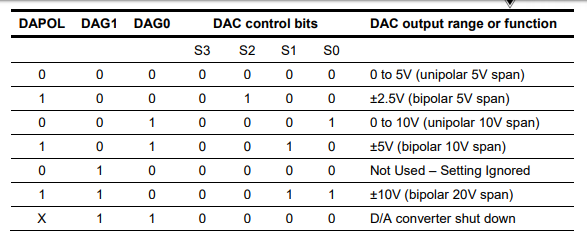
Page 2 Base + 14 Write DA Mode Configuration
This register defines the D/A output range. The control data sent to the D/A chip contains a 4 bit range / command instruction S3-0, whose value is defined based on the bits in this register according to the table below. When this register is written, the range command will be sent to the D/A according to the logic described here.
DAUR | DA unique range: 0 All D/A channels receive the same range selected by DAPOL and DAG1-0. 1 Only the D/A channel indicated by DACH1-0 should be set to the range selected by DAPOL and DAG1-0. |
DARCH1-0 | DA channel for selected range. If DAUR=0, these bits are ignored. If DAUR=1, these bits determine which D/A channel will have the range programmed according to DAPOL and DAG1-0. |
DAPOL | D/A polarity configuration |
DAG1-0 | D/A converter output range |
Page 2 Base + 14 Read DA Mode Configuration
DASIZE | This bit indicates the resolution of the D/A converter installed. The standard models of Helios all use a 12-bit DAC. 0 12-bit DAC 1 16-bit DAC |
Page 2 Base + 15 Write DAC MSB – 16-Bit Enhanced Mode
When DAMODE=1 (base+11 bit 6), the value written to this register forms the upper 8 bits of the 16-bit D/A value that is written to the D/A. When DAMODE=0, this register is ignored. This behavior is consistent regardless of the DASIZE value. DAMODE=1 should only be used when the 16-bit DAC is installed. The standard models of Helios use the 12-bit DAC.
DA15–8 D/A data bits 15 - 8; DA15 is the MSB.
Page 2 Base + 15 Read D/A Simultaneous Update
If DA simultaneous update is enabled (DASIM=1), reading this register will update the DAC outputs in both 12 and 16-bit mode. The value read back is 0.
Last updated