14.4.3 Page 1: AutoCalibration Control
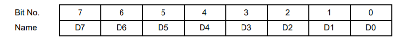
Page 1, Base + 12 Read/Write EEPROM / TrimDAC Data Register
During EEPROM or TrimDAC write operations, the data written to this register will be written to the selected device.
During EEPROM read operations this register contains the data to be read from the EEPROM and is valid after EEBUSY = 0.
The TrimDAC data cannot be read back.
Page 1, Base + 13 Read/Write EEPROM / TrimDAC Address Register
The EEPROM recognizes address 0 – 255 using address bits A7 – A0. The TrimDAC only recognizes addresses 0 – 7 using bits A2 – A0. In each case remaining address bits will be ignored.
Page 1, Base + 14 Write Calibration Control Register
This register is used to initiate various commands related to autocalibration.
Page 1, Base + 14 Read Calibration Status Register
Page 1, Base + 15 Write EEPROM Access Key Register
The user must write the key value 0xA5 (binary 10100101) to this register each time after any change in the states of registers bits PG1 and PG0 (base+1 bits 1-0) in order to get access to the EEPROM. This helps prevent accidental corruption of the EEPROM contents. Once the key value is written, access to the EEPROM remains enabled until the page bits are changed.
Last updated