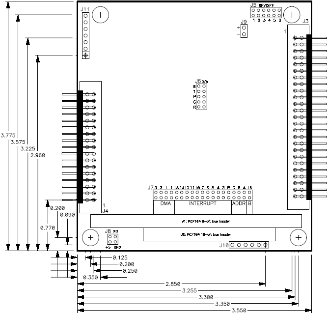
3. DMM-32DX-AT BOARD DRAWING
I/O Connectors and Features
J1 PC/104 8-bit bus header
J2 PC/104 16-bit bus header (only used for interrupt level)
J3 Analog I/O header (includes trigger and ctr/timer signals)
J4 Digital I/O header 5 Analog input single-ended / differential configuration
J6 D/A unipolar / bipolar / full-scale range configuration
J7 Base address / DMA level / interrupt level / bus width
J8 Digital I/O pull-up / pull-down configuration
J9 Test connector; not used in normal operation
J10 JTAG programming cable; not used in normal operation
J11 Auxiliary power connector
LED User-programmable LED
Last updated