6.11 Page 7: D/A Output Channel Control
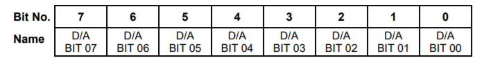
Page 7, Base + 12 Write D/A Output Low Byte
Page 7, Base + 13 Write D/A Output High Byte
These registers are used to write 16-bit data to the D/A. These registers function correctly regardless of whether the installed D/A is 12 bits or 16 bits. If data is written to page 7 base + 13, then the next time base + 5 is written, the FPGA will send the data from page 7 base + 12 & 13 to the channel selected by the channel bits in base + 5. After one such cycle, the FPGA will revert to using base + 4 & 5 for the D/A data until page 7 base + 13 is written to again.
Page 7, Base + 14 Write D/A Output Low Byte
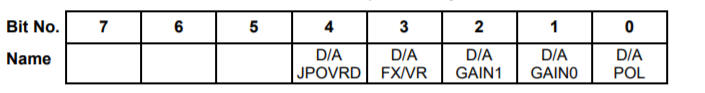
D/A JPOVRD | Selects control of the D/A converter between the hardware jumper settings of signals J_D/A FX/VR, J_D/A GAIN1, J_D/A GAIN0 and J_D/A POL or the register bits D/A FX/VR, D/A GAIN1, D/A GAIN0 and D/A POL here in Register 14. When set to ‘1’ use the contents of this register When set to ‘0’ use the jumpers on board. |
D/A FX/VR | Sets the D/A converter reference voltage to variable when ‘0’ or fixed when ‘1’. |
D/A GAIN1 | Sets the D/A converter output voltage gain. See table below. |
D/A GAIN0 | Sets the D/A converter output voltage gain. See table below. |
D/A POL | Sets the D/A converter polarity to unipolar when ‘0’ or bipolar when ‘1’. See table below. |
D/A GAIN1 | D/A GAIN0 | D/A POL | Description |
0 | 0 | 0 | 5V span (0 to +5V unipolar) |
0 | 0 | 1 | 5V span (-2.5V to +2.5V, bipolar) |
0 | 1 | 0 | 10V span (0 to +10V unipolar) |
0 | 1 | 1 | 10V span (-5V to 5V bipolar) |
1 | 0 | 0 | Not Used – Sets output to 0V |
1 | 0 | 1 | 20V span (-10V to +10V only) |
1 | 1 | 0 | Not Used – Sets output to 0V |
1 | 1 | 1 | D/A converter shut down |
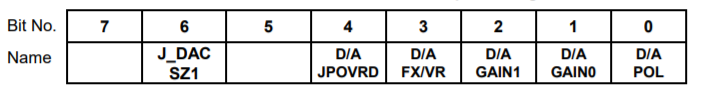
Page 7, Base + 14 Read D/A Hardware Jumper Configuration
J_DAC SZ1 Indicates the D/A converter size as indicated in the table below:
J_DAC SZ1 | Description |
0 | 16 bits |
1 | 12 bits |
D/A JPOVRD | Indicates status of the control of the D/A converter between the hardware jumper settings of signals J_D/A FX/VR, J_D/A GAIN1, J_D/A GAIN0 and J_D/A POL or the register bits D/A FX/VR, D/A GAIN1, D/A GAIN0 and D/A POL here in Register 14. When set to ‘1’ use the write contents of this register When set to ‘0’ use the jumpers on the board. |
D/A FX/VR | Set the D/A converter reference voltage to variable when ‘0’ or fixed when ‘1’. |
D/A GAIN1 | Indicates the D/A converter output voltage gain setting. See table above. |
D/A GAIN0 | Indicates the D/A converter output voltage gain setting. See table above. |
D/A POL | Indicates the D/A converter polarity is set to unipolar when ‘0’ or bipolar when ‘1’. See table above. |
Last updated