4. FUNCTIONAL OVERVIEW
The following section provides functional details of the key sub-systems implemented on the Floyd SC carrier board.
4.1 Power Supply Specification
The Floyd SC carrier board accepts a wide input voltage range of +12V to +24V. Maximum power consumption with either Nano or NX module installed and all peripherals operating is W. The maximum allowable reflected ripple, measured at the voltage input connector is 50 mV p-p. The input power is provided via a barrel jack with 5.5mm OD / 2.5mm ID dimensions (tip positive).
4.2 Camera Serial Interface
The board supports three MIPI CSI x2 cameras which are interfaced through 15-pin connectors. The supporting signals like I2C and control signals for the CSI are available through connector so that user can directly interface the camera to the board. All the connectors support dual-lane CSI channels.
Driver support is available for only 2 Cameras simultaneously. Driver support for 3rd camera can be provided based on customer request.
4.3 Controller Area Network (CAN)
The carrier board is equipped with a CAN interface. The interface is implemented either with a non-isolated transceiver PCA82C251T/YM,118 (standard) or an isolated transceiver ADM3053BRWZ (optional, contact Diamond Systems Sales for further information). The CAN feature is available only with the NX module installed; the Nano module does not include an integrated CAN controller.
4.4 Digital IO
The board provides 16x digital I/Os , which are individually configurable as an output or input. Digital I/Os are realized using an I2C GPIO expander. The I2C control for the expander is directly fed from the module. This I2C GPIO expander can support both 3.3V and 5V, so a voltage translator is used to between module and I2C GPIO expander. This expander device is accessible on the I2C address 0x22. The IO voltage is selectable using jumper setting refer section 9.1 for Jumper configuration details.
The I/Os are made available on a 2x10 2.54mm header.
4.5 Display
Floyd SC supports two display options:
HDMI 2.0a/b video with audio with both Nano and NX modules.
DP 1.4 video, audio supported with NX module only.
The HDMI is terminated on an upright HDMI connector & the DP is terminated on an upright DP connector.
4.6 Ethernet Ports
Floyd SC is equipped with one or two Gigabit Ethernet ports:
1. (all models) A 10/100/1000 Ethernet port routed from the module.
2. (FLD-SCBB-02 model only) A 10/100/1000 Ethernet port derived from the Intel WGI210IT/Intel I210 PCIe Ethernet controller when used with Xavier/TX2 NX module
Both Ethernet ports are accessed via two RJ-45 jacks. The magnetics needed for these ports are available on the Floyd SC carrier. The jacks indicate Link and speed status associated with each port using integrated LEDs.
When PCIe on Expansion connector is supported the 2nd Ethernet port will not be available.
4.7 LED Indicators
The board provides the following LED indicators. All LEDs are located near to board edge or their respective features on the Topside of the PCB. All LEDs are labeled in silkscreen with their function.
General | Description |
PWIN | Power IN indicator |
PWGD | Power Good indicator |
USER | User control, demonstrates board is working |
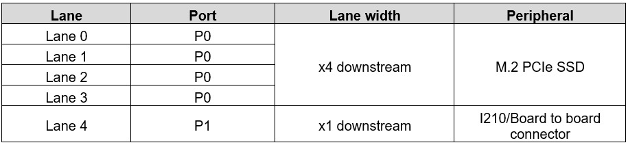
4.8 PCIe Link Routing
The base board utlilizes the PCIe lanes from the module as per below table:
Lane 4 is available only with NX module.
4.8 M.2 Socket
Floyd SC board has an M.2 M-Key socket that supports either 2280 (22 mm wide and 80 mm long) or 2242 form-factor (22 mm wide and 42 mm long) Non-Volatile Memory Express (NVMe) SSD add-in card. All PCIe x4 lane available from module is routed to the M.2 socket.
4.9 Expansion connector
Floyd SC board provides an option for additional interfaces through an expansion connector.
Signals routed to Expansion connector are 1 lane PCIe available from module (available only when used with NX module), 1 USB 3.0, 1 USB 2.0 and SDIO signals.
When 2nd Ethernet port and USB3.0 connector is used on Floyd SC card the interfaces on expansion connectors will not be available.
4.10 Serial Port Interfaces
The Floyd SC baseboard provides two serial ports, one with jumper selectable RS232 or RS485 protocol modes and one dedicated RS232. Since the serial ports from module are 1.8V complaint, they are level shifted to 3.3V logic before feeding to the transceivers.
4.11 USB Ports
Floyd SC provides 2x USB 2.0 ports and 1x USB 3.0 port.
2x USB 2.0 ports are available on a vertically stacked dual-port USB 2.0 connector.
The upper USB 2.0 port (USB0) can be used for programming during recovery mode.
1x USB 3.0 port terminates on an upright right-angle USB 3.0 connector. This connector also supports the USB 2.0 protocol.
The USB signals connected to upright USB3.0 connector is optionally connected to expansion connector using 0 Ohm resistors.
4.12 Utility Connector
A 2x10 Utility Header connector on Floyd SC implements the Power button, Reset, SPI, Force Recovery, Debug TTL UART, and I2C signals. Momentary switches are also provided along the front board edge for Reset and Recovery functions. These features can be accessed via either connection.
Last updated