13. DATA ACQUISITION SUBSYSTEM
This page describes the Data Acquisition subsystem available on Athena IV.
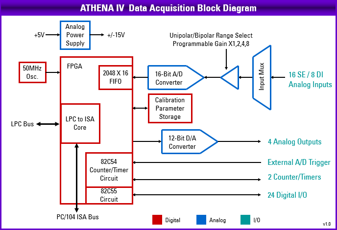
The block diagram of the DAQ subsystem on Athena IV is shown below:
Athena IV contains a data acquisition subsystem consisting of A/D, D/A, digital I/O, and counter/timer features. This subsystem is equivalent to a complete add-on data acquisition module.
The A/D section includes a 16-bit A/D converter, 16 input channels, and a 2048-sample FIFO. Input ranges are programmable, and the maximum sampling rate is 200KHz. The D/A section includes four 12-bit D/A channels. The digital I/O section includes 24 lines with programmable direction. The counter/timer section includes a 24-bit counter/timer to control A/D sampling rates and a 16-bit counter/timer for user applications.
High-speed A/D sampling is supported with interrupts and a FIFO. The FIFO is used to store a user-selected number of samples, and the interrupt occurs when the FIFO reaches this threshold. Once the interrupt occurs, an interrupt routine runs and reads the data out of the FIFO. In this way the interrupt rate is reduced by a factor equal to the size of the FIFO threshold, enabling a faster A/D sampling rate. The circuit can operate at sampling rates of up to 200KHz, with an interrupt rate of 6.6-10KHz.
The A/D circuit on Athena IV can be accessed at four different addresses. These addresses are jumper selectable as described in Section 12.4 ISA Base Address at JP6. The base address selection provides flexibility to the user to avoid address conflicts while using multiple external ISA cards having similar addresses. By default, the A/D circuit is accessible at address 0x280.
The A/D IRQ can be routed to ISA IRQ4, or IRQ5. The IRQs are jumper selectable as described in Section 12.5 ISA IRQ at JP6. As with ISA addresses, multiple IRQ availability helps to resolve conflicts. By default, the A/D IRQ is set to 5.
Last updated