6.7 Page 3: Autocalibration Registers
These registers are used to control the autocalibration process. For user software-controlled autocalibration (as with the DMM-32-AT), these registers are used by the Universal Driver software or the user’s software to manage the calibration process. For auto-autocalibration, the onboard dsPIC microcontroller uses these registers to manage the autocalibration automatically.
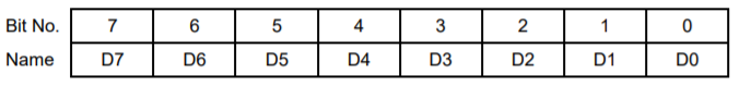
Page 3, Base + 12 Read/Write EEPROM / TrimDAC Data Register
D7-0 | Calibration data to be read or written to the EEPROM and/or TrimDAC. During EEPROM or TrimDAC write operations, the data written to this register will be written to the selected device. During EEPROM read operations this register contains the data to be read from the EEPROM and is valid after EEBUSY = 0. The TrimDAC data cannot be read back. |
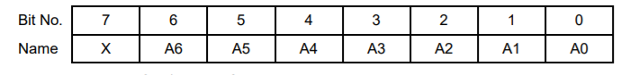
Page 3, Base + 13 Read/Write EEPROM / TrimDAC Address Register
A6-A0 | EEPROM / TrimDAC address. The EEPROM recognizes address 0 – 127 using address bits A6 – A0 of this register. The TrimDAC only recognizes addresses 0 – 7 using bits A2 – A0. In each case remaining address bits will be ignored. |
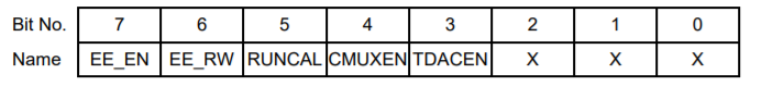
Page 3, Base + 14 Write Calibration Control Register
This register is used to initiate various commands related to autocalibration. More detailed information on autocalibration may be found elsewhere in this manual.
EE_EN | EEPROM Enable. Writing a 1 to this bit will initiate a transfer to/from the EEPROM as indicated by the EE_RW bit. |
EE_RW | Selects read or write operation for the EEPROM: 0 = Write, 1 = Read. |
RUNCAL | Writing 1 to this bit causes the board to reload the calibration settings from EEPROM. |
CMUXEN | Calibration multiplexor enable. The cal mux is used to read precision on-board reference voltages that are used in the autocalibration process. It also can be used to read back the value of analog output 0. |
1 | enable cal mux and disable user analog input channels |
0 | disable cal mux, enable user inputs |
TDACEN | TrimDAC Enable. Writing 1 to this bit will initiate a transfer to the TrimDAC (used in the autocalibration process). |
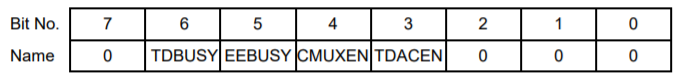
Page 3, Base + 14 Read Calibration Status Register
TDBUSY | TrimDAC busy indicator |
0 | User may access TrimDAC |
1 | TrimDAC is being accessed; user must wait |
EEBUSY | EEPROM busy indicator |
0 | User may access EEPROM |
1 | EEPROM is being accessed; user must wait |
CMUXEN | Calmux enable status |
0 | Calibration multiplexor is not currently enabled |
1 | Calibration multiplexor is enabled and may be updated |
TDACEN | TrimDAC enable status |
0 | TrimDAC is not enabled |
1 | TrimDAC is enabled and may be updated |
Page 3, Base + 15 Write Advanced Feature Access Register
After entering page 3 by setting the Page bits, the user must write the value 0xA5 (binary 10100101) to this register in order to get access to the EEPROM. This helps prevent accidental corruption of the EEPROM contents. Once the page is set and this value is written, you can make unlimited reads and writes to the EEPROM without resending this key as long as you stay on page 3.
Writing 0xA6 to this register enables enhanced mode, and writing 0xA7 to this register disables enhanced mode. The default power-on state is disabled. Enhanced mode consists of the following:
Pages 2, 4, 5, and 6 are accessible.
Writing 0xA7 to this register disables all enhanced features. This is the default power-on state. Writing 0xA7 to this register automatically halts any enhanced feature currently running, internally clears all enhanced registers to their default state, and resets the A/D FIFO depth to 512.
Page 3, Base + 15 Read FPGA Revision Code
This register indicates the revision level of the FPGA design. This value may change with new revisions of the FPGA, so its value cannot be predicted. It is provided as a way to distinguish between different versions of FPGA code.
Last updated