7. CONNECTOR AND JUMPER LOCATIONS
This page describes the connector & jumper locations on the Floyd SC carrier card.
7.1 Main Component Locations
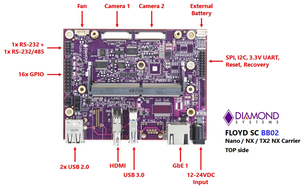
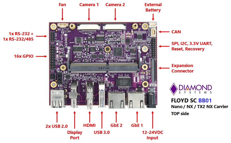
Following figure depicts the top callout view of the Floyd SC carrier board indicating the component locations.
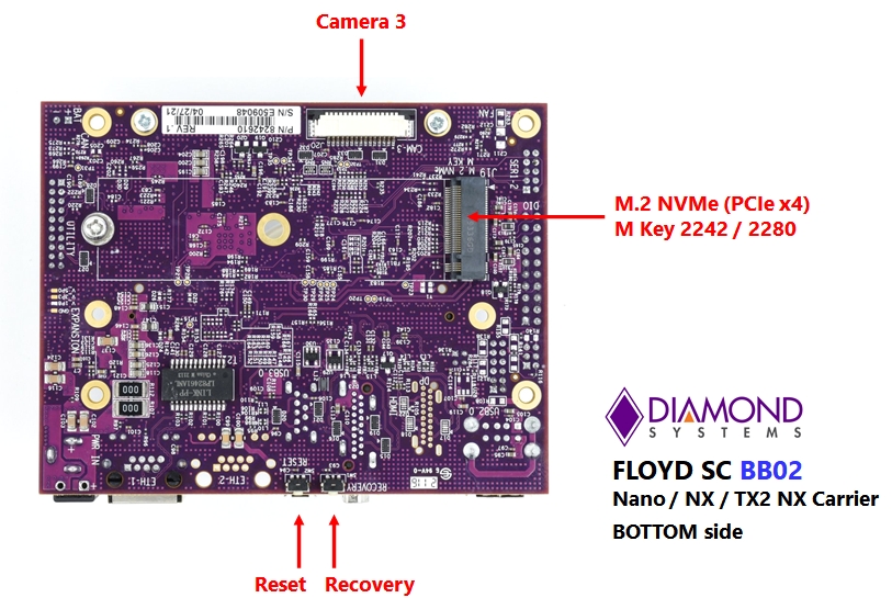
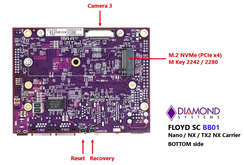
Following figure depicts the bottom callout view of the Floyd carrier board indicating the component locations.
7.2 IO Connectors, Jumpers and LED Specifications
The following table lists the I/O connectors marked in section 7.2 and their corresponding functions.
Connector | Function |
J2 | Power In |
J3 | Ethernet 1 |
J4 | Ethernet 2 |
J5 | USB 2.0 |
J6 | HDMI |
J7 | USB 3.0 |
J8 | DP |
J10 | Module |
J11 | DIO |
J12 | Utility |
J13 | Serial 1 & 2 |
J14 | CAN |
J15 | Camera 1 |
J16 | Camera 2 |
J17 | Fan |
J18 | Battery |
J20 | Camera 3 |
The following table lists the Jumpers marked in section 7.1 and their corresponding functions.
Jumper | Function |
JP1 | Digital I/O Pull Up/Down |
JP2 | Protocol Mode Selection, Serial Termination |
JP3 | USB2.0 port 1 Host/Device Select |
The following table lists the LEDs marked in section 7.1 and their corresponding functions.
LED Block 1 | Description |
PWIN | Power In |
PWGD | Power Good |
USER | User LED |
7.3 Front-Facing Connector
Front Facing image to be updated.
7.4 Expansion Slot and Switch Locations
The following table lists the connectors and switches marked in Figures in section 7.1 and their corresponding functions.
Connector | Function |
SW1 | RECOVERY |
SW2 | RESET |
J9 | Expansion connector |
J19 | USB 2.0 |
Last updated