4.1 Analog I/O Header – J3
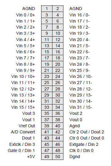
Diamond-MM-32DX-AT provides a 50-pin header on the right edge of the board labeled J3 for all I/O relating to analog functions. Pin 1 is in the upper left corner.
Last updated
Diamond-MM-32DX-AT provides a 50-pin header on the right edge of the board labeled J3 for all I/O relating to analog functions. Pin 1 is in the upper left corner.
Last updated
Signal Name
Definition
Vin 15/15+ ~ Vin 0/0+
Analog input channels 15 - 0 in single-ended mode; High side of input channels 15 - 0 in differential mode
Vin 31/16- ~ Vin 15/0-
Analog input channels 31 - 16 in both single-ended mode; Low side of input channels 15 - 0 in differential mode
Vref Out
Precision +5V signal for reference only. Do not use for power
Vout 0 - 3
16-bit standard, (12-bit optional) analog output channels
A/D Convert
A/D convert signal output; can be used to synchronize multiple boards
Dout 2 – Dout 0
Digital output port with counter/timer functions
Din 3 – Din 0
Digital input port with counter/timer and external trigger functions
Extclk
External A/D trigger input; Also used for digital interrupt (DINT) input
Extgate
Pin to control gating of Ctrs 1& 2 for A/D timing
Gate 0
Pin to control gating of Ctr 0
Clk 0
Input source to Ctr 0
+5V
Connected to PC/104 bus power supply
Agnd
Analog ground; connected to digital ground at a single point at DC/DC converter PS1 on board
Dgnd
Digital ground; connected to PC/104 bus ground