16.1 Introduction
This chapter describes the steps involved in performing an A/D conversion on a selected input channel using direct programming (without the driver software). Perform an A/D conversion according to the following steps. Each step is discussed in detail below.
Select the input channel range.
Select the input range and scan option.
Select the polarity.
Wait for analog input circuit to settle.
Initiate an A/D conversion.
Wait for the conversion to finish.
Read the data from the board.
Convert the numerical data to volts or engineering units.
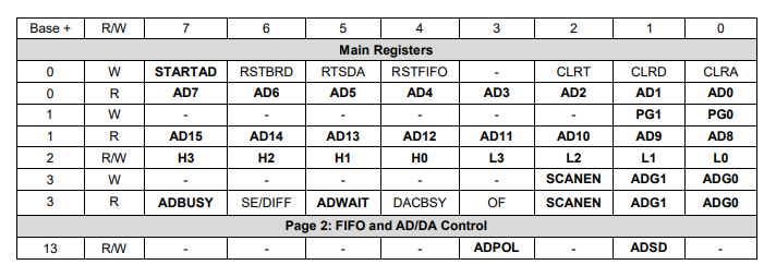
The control registers associated with A/D conversions are provided below for reference:
STARTAD | Write a 1 to this bit to start an A/D conversion or scan |
AD15-0 | A/D data value |
PG1-0 | Selects page 0, 1, or 2 at addresses base+12 through base+15 |
H3-0 | High channel of selected A/D channel range |
L3-0 | Low channel of selected A/D channel range |
SCANEN | A/D scan enable: 0 = single sample each trigger, 1 = scan of all channels each trigger |
ADG1-0 | A/D gain setting, see table in section 15.2 |
ADBUSY | A/D busy indicator: 0 = A/D is idle; 1 = A/D is busy, must wait for completion |
ADWAIT | A/D circuit settling indicator: 0 = circuit is idle, conversion can start; 1 = circuit is busy, must wait |
ADPOL | A/D polarity configuration: 0 = Bipolar, 1 = Unipolar |
ADSD | A/D single-ended / differential configuration: 0 = Single-ended, 1 = Differential |
Last updated