22. COUNTER/TIMER OPERATION
The AV model of Helios with data acquisition contains two counter/timers that provide various timing functions on the board for A/D timing and user applications. These counters are controlled with registers in the on-board data acquisition controller FPGA. Base+4 includes counter configuration bits, and base+11 contains the configuration bit DIOCTR, which controls 4 dual-function I/O pins on the data acquisition connector J17.
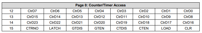
Register Map for Counter/Timer Circuit
CTRD23-0 | 24-bit divisor or latch value for Counter 0 |
CTRD15-0 | 16-bit divisor or latch value for Counter 1 |
CTRNO | Counter no. for command, 0 or 1 |
Latch | Latch the selected counter so that its value may be read. The counter must be latched before it is read. Reading from registers at page 0, base+12 thru base+14 returns the most recently latched or loaded value. If you are reading the 16-bit Counter 1 data, read only page 0, base+12 and base+13. Any data in page 0, base+14 will be from the previous 24-bit Counter 0 operation. |
GTDIS | Disable external gating for the selected counter (see GTEN below). |
GTEN | Enable external gating for the selected counter. If enabled, the associated J17 connector input signal GATE0 or GATE1 controls counting on the counter. If the GATEn signal is high, counting is enabled. If the GATEn signal is low, counting is disabled. |
CTDIS | Disable counting on the selected counter. The counter will ignore input pulses. |
CTEN | Enable counting on the selected counter. The counter will decrement on each input pulse |
LOAD | Load the selected counter with the data written to page 0, base+12 through base+14 (Counter 0) or page 0, base+12 and base+13 (Counter 1). |
CLR | Clear the current counter (set its value to 0). Counter operation such as count enable or gate enable is not affected by the CLR command. If the counter is enabled it will continue to count input pulses. |
Last updated