26.PANEL I/O BOARD
The Helios Panel I/O Board, model PNL-HLV-02, provides a convenient way to access most of the SBC’s I/O features without the use of cables. The bottom side contains 2mm female sockets on the bottom side that plug on top of the SBC and convert the SBC I/O pin headers to industry-standard connectors on the top side. Available I/O includes:
4 serial ports
4 USB ports
VGA
Ethernet
Keyboard & mouse
16 digital I/O from Vortex CPU
Data acquisition from Helios model HLV800-256AV
The panel I/O board may be used together with the Helios SBC in an “open frame” configuration, or the assembly can be installed in a Pandora enclosure to create a complete, cable-free, compact industrial computer. Pandora is available in multiple lengths to allow the installation of PC/104 add-on modules below the Helios SBC to provide additional functionality in the system.
The PNL-HLV-02 includes two built-in expansion options to enable the use of additional boards inside the enclosure without requiring customization of the enclosure front panel or panel board. Additional boards are installed below the Helios SBC using the stacking PC/104 connector:
A 50-pin latching connector enables access to one additional I/O board inside the enclosure. A 50-pin header on the bottom of the board is used to bring out the I/O from the installed PC/104 board with a ribbon cable. Any I/O board with a 50-pin connector can be easily attached, or a custom cable can be made to mate the I/O board’s connector to the 50-pin header on the panel board.
Two DB9M connectors on the front panel enable the use of 2 additional serial ports, for a total of 6. The additional serial ports are provided by installing a Diamond Systems’ EMM-4M-XT board. A 20-pin connector on the bottom of the panel board is used to bring out the serial ports with a 20-pin ribbon cable.
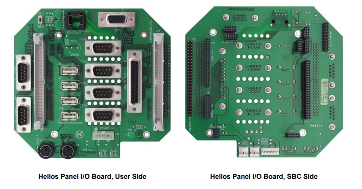
In the photo at left, the 50-pin connector on the far right and the two DB9M connectors on the far left are the user accessible expansion connectors. In the photo at right, the 50-pin header on the far left and the 20-pin header in the upper right are the internal connections for the add-on modules.
Last updated