23.WATCHDOG TIMER
The watchdog timer can be used to trigger an interrupt or system reset upon the expiration of a programmed time interval. The purpose of this timer is to enable the system to recover from a software or hardware error that causes the system to freeze or get caught up in a software infinite loop.
The watchdog timer uses I/O address range 0x67 – 0x6D. It uses a 24-bit down counter for the timeout interval, with a resolution of 30.5usec. The shortest timeout interval is 30.5us, and the longest timeout interval is 30.5us x 2 24 = 511 sec.
To use the watchdog timer, first make sure it is enabled in the BIOS. The default setting is enabled. Go to Chipset then South Bridge Configuration and select Watchdog Configuration. Set WDT1 to Enabled.
Once WDT1 is enabled, the steps are as follows: First program the desired timeout interval, then select the timeout event, then enable the timer. Once the timer is enabled, the software must reset it before it times out, or else the timeout event will occur. This reset must occur repeatedly until the watchdog timer is disabled.
The steps to set up and use the watchdog timer are as follows:
Write the desired time delay into registers 0x6A – 0x6C (0x6A is the LSB).
Select timer reset event using register 0x69.
Set register 0x68 bit 6 (0x40) to enable the timer.
To retrigger the timer and prevent the selected event from occurring, write any value to register 0x67 before the timer reaches zero. This procedure must repeat indefinitely as long as the timer is enabled.
To determine if a timeout event has occurred, monitor bit 7 of register 0x6D. To reset this event indicator, write a 1 to this bit (0x80). This is a convenience function. The software must provide the appropriate interrupt service routine etc. to respond to the timeout event if and when it occurs.
To disable the timer, clear bit 6 in register 0x68. The detailed register information for the WDT is provided below. Register bits marked “-“ are unused.
0x67 Write WDT Reload / Reset
When the watchdog timer is enabled, the software must write to this register before the timer times out to prevent the selected timeout function from occurring. The value written does not matter.
When this register is written, the timer will reload to its original value and begin to count down again.
0x68 Write WDT Enable Register
WDTEN Watchdog timer enable:
0 Disable WDT operation; timeout event will not occur.
1 Enable WDT operation; timeout event will occur if WDT is not retriggered before it times out.
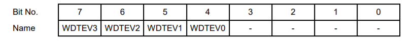
0x69 Write WDT Timeout Event
WDTEV3-0 Selects the event to occur upon timeout:
Binary | Hex | Signal/Function |
0000 | 0 | Invalid Setting |
0001 | 1 | IRQ3 |
0010 | 2 | IRQ4 |
0011 | 3 | IRQ5 |
0100 | 4 | IRQ6 |
0101 | 5 | IRQ7 |
0110 | 6 | IRQ9 |
0111 | 7 | IRQ10 |
1000 | 8 | Invalid Setting |
1001 | 9 | IRQ12 |
1010 | A | IRQ14 |
1011 | B | IRQ15 |
1100 | C | NMI Non-maskable interrupt |
1101 | D | System Reset |
1110 | E | Invalid Setting |
1111 | F | Invalid Setting |
0x6A Write WDT Timeout Interval Low Byte
WDTD7-0 The lowest 8 bits of the 24-bit timeout interval
0x6B Write WDT Timeout Interval Middle Byte
WDTD16-8 The middle 8 bits of the 24-bit timeout interval
0x6C Write WDT Timeout Interval High Byte
WDTD23-16 The highest 8 bits of the 24-bit timeout interval
0x6D Write/Read WDT Timeout Indicator
WDTTO When this bit is 1, a timeout occurred on the watchdog timer. Write a 1 to this bit to reset the timeout indicator.
Last updated