User Manuals
  • SBCs
    • Athena-IV
      • Hardware User Manual
        • TABLE OF CONTENTS
        • 1. IMPORTANT SAFE HANDLING INFORMATION
        • 2. INTRODUCTION & PRODUCT VARIANTS
        • 3. MODULE FEATURES
        • 4. FUNCTIONAL OVERVIEW
        • 5. BLOCK DIAGRAM
        • 6. MECHANICAL DRAWING
        • 7. CONNECTOR, LED & JUMPER LOCATIONS
        • 8. I/O CONNECTORS, JUMPERS and LEDs REFERENCE TABLES
        • 9. CONNECTOR PINOUTS
        • 10. I/O CONNECTORS & CABLES LIST
        • 11. I/O EXPANSION & CoM Express SOCKETS
        • 12. JUMPER DESCRIPTION
        • 13. DATA ACQUISITION SUBSYSTEM
          • DAQ Register Map
          • Analog to Digital Converter
          • Digital to Analog Converter
          • Digital I/O Operation
          • Counter/Timer Operation
          • Serial Port Protocol Mode Select
        • 14. GETTING STARTED
        • 15. HEAT SINK
        • 16. SPECIFICATIONS
        • 17. ORDERING GUIDE
        • 18. LIMITED WARRANTY POLICY
      • Windows 10 BSP Manual
        • Windows 10 64-Bit
          • 1. INTRODUCTION
          • 2. SCOPE
          • 3. TARGET HARDWARE REQUIREMENTS
          • 4. SYSTEM REQUIREMENTS
            • 4.1 Development computer
          • 5. FEATURES AND DRIVER DETAILS
          • 6. CUSTOMIZING AND DEPLOYING A RUN-TIME IMAGE
            • 6.1 To add driver to an offline image by using DISM tool
            • 6.2 To remove driver from and offline image by using DISM tool
            • 6.3 To find available windows feature in image
            • 6.4 To enable windows feature
            • 6.5 To disable windows feature
            • 6.6 Creating a USB installation media
            • 6.7 Extracting WIM File
            • 6.8 Flashing Windows 10 BSP image
            • 6.9 Using the Final image
            • 6.10 Booting to Windows Welcome mode.
          • 7. APPENDIXES
            • 7.1 Appendix A: Steps to make USB/ M.2 2230 SATA drive bootable:
            • 7.2 Appendix B: Steps to test FTP Server:
            • 7.3 APPENDIX C: STEPS TO CREATE WINPE BOOTABLE USB DRIVE
            • 7.4 APPENDIX D: WINDOWS 10 LICENSE ACTIVATION
            • 7.5 APPENDIX E: STEPS TO TEST OS PRODUCT KEY LICENSE:
            • 7.6 APPENDIX F: WINDOWS 10 IMAGE RE-FLASHING
            • 7.7 APPENDIX G: STEPS TO FORMAT M.2 2230 SATA
      • Linux BSP Manual
        • Linux 64-Bit
          • 1. Introduction
            • 1.1 Warranty / Disclaimer
            • 1.2 Linux License and Support Information
          • 2 BSP Contents
            • 2.1 Manual
            • 2.2 M.2 2230 SATA disk
            • 2.3 Backup copy on DVD with image
          • 3 Quick Start Guide
          • 4 Linux Features
            • 4.1 Baseline Linux Distribution
            • 4.2 Installed Applications
            • 4.3 Classic GUI view
            • 4.4 Application / Feature Configuration
            • 4.5 FTP Server Enable Instructions
            • 4.6 HTTP Server Enable Instructions
          • 5. Reimaging a Corrupted Flashdisk
          • 6 Reinstalling Linux
            • 6.1 Basic Linux installation
            • 6.2 Configuring Linux to match the provided runtime image
          • 7 Linux Passwords
          • 8 Troubleshooting
            • 8.1 Using built-in ‘fsck’ to fix disk
            • 8.2 Using SSD on separate desktop PC to recover files or perform file-system check ‘fsck’
            • 8.3 Connecting VGA monitor if LCD or other display support fails
          • 9 Appendices
            • Appendix A: Ubuntu 20.04.1 Installation Steps
            • Appendix B: Configuration of FTP Server
            • Appendix C: Configuration of HTTP server
            • Appendix D: Configuration of SSH server
            • Appendix E: File Transfer through minicom
            • Appendix F: File Reception through minicom
            • Appendix G: DD command for image Backup
            • Appendix H: To create and change of Root user password, Ubuntu new user creation
            • Appendix I: Disable check for updates
            • Appendix J: Install additional utilities in Ubuntu OS
            • Appendix K: Automatic login option
            • Appendix L: Sound recording
            • Appendix M: Linux Image RE-flashing
    • Aries
      • QNX BSP Manual
        • QNX 7.0 32-Bit
          • 1. INTRODUCTION
          • 2. BSP CONTENTS
          • 3. QUICK START GUIDE
          • 4. REIMAGING A CORRUPTED FLASHDISK
          • 5. QNX PASSWORDS
          • 6. Universal Driver
            • 6.1 Overview
            • 6.2 Steps to execute demo application
          • 7. TROUBLESHOOTING
            • 7.1 Checking BIOS to ensure BSP disk is selected in boot disk priority
            • 7.2 Resetting BIOS options to optimal defaults if many options were handled/changed
            • 7.3 Connecting VGA monitor if LCD or other display support fails
          • APPENDIX A: TESTING FTP SERVER
          • APPENDIX B: SERIAL PORT CONFIGURATION
            • Step 1: Serial port configuration in BIOS Settings
            • Step 2: Baud Rate configuration in QNX
            • Step 3: Serial Port Data Transfer Commands
            • Step 4: Serial Port Data Receiver Commands
          • APPENDIX C: AUDIO TESTING
          • APPENDIX D: ETHERNET TESTING
            • Step 1: Ethernet Connection in LAN Controller1
            • Step 2: Ethernet Connection in LAN Controller2
          • APPENDIX E: USB FILE TRANSFERS
            • Step 1: Mount QNX6 Filesystem based USB
            • Step 2: Mount DOS Filesystem based USB
            • Step 3: Copy Command
            • Step 4: Unmount the USB
            • Step 5: Checking Storage space of system
          • APPENDIX F: GRAPHICS CONFIGURATION
            • Step 1: Enable Display Devices
            • Step 2: Putty Setup
            • Step 3: Graphics Configuration File Setup
            • Step 4: Start Screen to run graphics
            • Step 5: Running Graphic Animation Applications
              • Gears Application
              • Sync Application
              • ShareWin Application
            • Step 6: Display Image
          • APPENDIX G: NEW USER CREATION AND CHANGING EXISTING USER ACCOUNT PASSWORD
            • Step 1: Steps to change existing user accounts password
            • Step 2: Steps to create new user
          • APPENDIX H: QNX IMAGE RE-FLASHING
      • Watchdog Timer Configuration Steps User Manual
        • 1. Watchdog Timer Operation
        • 2. Watchdog Timer Register Map
        • 3. Watchdog Timer Configuration Steps
    • Gemini
      • Hardware User Manual
        • 1. IMPORTANT SAFE HANDLING INFORMATION
        • 2. QUICK START GUIDE
        • 3. INTRODUCTION & PRODUCT CONFIGURATIONS
        • 4. MODULE FEATURES
        • 5. FUNCTIONAL OVERVIEW
        • 6. BLOCK DIAGRAM
        • 7. MECHANICAL DRAWING
        • 8.FEATURE LOCATIONS
        • 9. FEATURE REFERENCE TABLE
        • 10. CONNECTOR PINOUT SPECIFICATION
        • 11. I/O CONNECTOR LIST
        • 12. JUMPER DESCRIPTION
        • 13. LED DESCRIPTION
        • 14. PCI-104 AND PCIe/104 BOARD INSTALLATION
        • 15. SYSTEM ASSEMBLY
        • 16. HEAT SPREADER
        • 17. DIGITAL I/O
        • 18. SERIAL PROTOCOL SELECTION
        • 19. SPECIFICATIONS
        • 20. SOFTWARE SPECIFICATIONS
        • 21. ORDERING INFO
        • 22. LIMITED WARRANTY POLICY
      • Windows 10 BSP Manual
        • Windows 10 64-Bit
          • 1. INTRODUCTION
          • 2. SCOPE
          • 3. TARGET HARDWARE REQUIREMENTS
          • 4. SYSTEM REQUIREMENTS
            • 4.1 Development Computer
          • 5. FEATURES AND DRIVER DETAILS
          • 6. CUSTOMIZING AND DEPLOYING A RUN-TIME IMAGE
            • 6.1 To add driver to an offline image by using DISM tool
            • 6.2 To remove driver from and offline image by using DISM tool
            • 6.3 To find available windows feature in image
            • 6.4 To enable windows feature
            • 6.5 To disable windows feature
            • 6.6 Creating a USB installation media
            • 6.7 Extracting WIM File
            • 6.8 Flashing Windows 10 BSP image
            • 6.9 Using the Final image
            • 6.10 Booting to Windows Welcome mode.
          • 7. APPENDIXES
            • 7.1 Appendix A: Steps to make USB/ M.2 2242 drive bootable:
            • 7.2 Appendix B: Steps to test FTP Server:
            • 7.3 Appendix C: Steps to create WinPE bootable USB drive:
            • 7.4 Appendix D: Windows 10 License Activation
            • 7.5 Appendix E: Steps to test OS Product key License:
            • 7.6 Appendix F: Windows 10 Image Re-flashing
            • 7.7 Appendix G: Steps to format M.2 2242
      • Linux BSP Manual
        • Linux 64-Bit
          • 1. INTRODUCTION
            • 1.1 Warranty / Disclaimer
            • 1.2 Linux License and Support Information
          • 2. BSP CONTENTS
            • 2.1 Manual
            • 2.2 SATA disk
            • 2.3 Backup copy on DVD with image
          • 3. QUICK START GUIDE
          • 4. LINUX FEATURES
            • 4.1 Baseline Linux Distribution
            • 4.2 Installed Applications
            • 4.3 Classic GUI view
            • 4.4 Application / Feature Configuration
            • 4.5 FTP Server Enable Instructions
            • 4.6 HTTP Server Enable Instructions
          • 5. REIMAGING A CORRUPTED FLASHDISK
          • 6. REINSTALLING LINUX
            • 6.1 Basic Linux installation
            • 6.2 Configuring Linux to match the provided runtime image
          • 7. LINUX PASSWORDS
          • 8. TROUBLESHOOTING
            • 8.1 Using built-in ‘fsck’ to fix disk
            • 8.2 Using SSD on separate desktop PC to recover files or perform file-system check ‘fsck’
            • 8.3 Connecting VGA monitor if LCD or other display support fails
          • APPENDIX A: UBUNTU 20.04.1 INSTALLATION STEPS
          • APPENDIX B: CONFIGURATION OF FTP SERVER
          • APPENDIX C: CONFIGURATION OF HTTP SERVER
          • APPENDIX D: CONFIGURATION OF SSH SERVER
          • APPENDIX E: FILE TRANSFER THROUGH MINICOM
          • APPENDIX F: FILE RECEPTION THROUGH MINICOM
          • APPENDIX G: DD COMMAND FOR IMAGE BACKUP
          • APPENDIX H: TO CREATE AND CHANGE OF ROOT USER PASSWORD, UBUNTU NEW USER CREATION.
          • APPENDIX I: DISABLE CHECK FOR UPDATES
          • APPENDIX J: INSTALL ADDITIONAL UTILITIES IN UBUNTU OS
          • APPENDIX K: AUTOMATIC LOGIN OPTION
          • APPENDIX L: SOUND RECORDING
          • APPENDIX M: LINUX IMAGE RE-FLASHING
    • Saturn
      • Windows 10 BSP Manual
        • Windows 10 64-Bit
          • 1. INTRODUCTION
          • 2. SCOPE
          • 3. TARGET HARDWARE REQUIREMENTS
          • 4. SYSTEM REQUIREMENTS
            • 4.1 Developement Computer
          • 5. FEATURES AND DRIVER DETAILS
          • 6. CUSTOMIZING AND DEPLOYING A RUN-TIME IMAGE
            • 6.1 To add driver to an offline image by using DISM tool
            • 6.2 To remove driver from and offline image by using DISM tool
            • 6.3 To find available windows feature in image
            • 6.4 To enable windows feature
            • 6.5 To disable windows feature
            • 6.6 Creating a USB installation media
            • 6.7 Extracting WIM File
            • 6.8 Flashing Windows 10 BSP image
            • 6.9 Using the Final image
            • 6.10 Booting to Windows Welcome mode.
          • 7. APPENDICES
            • 7.1 Appendix A: Steps to make USB/ M.2 2242 drive bootable
            • 7.2 Appendix B: Steps to test FTP Server
            • 7.3 Appendix C: Steps to create WinPE bootable USB drive
            • 7.4 Appendix D: Windows 10 License Activation
            • 7.5 Appendix E: Steps to test OS Product key License
            • 7.6 Appendix F: Windows 10 Image Re-flashing
            • 7.7 Appendix G: Steps to format M.2 2242
      • Linux BSP Manual
        • Linux 64-Bit
          • 1. Introduction
            • 1.1 Warranty / Disclaimer
            • 1.2 Linux License and Support Information
          • 2. BSP Contents
            • 2.1 Manual
            • 2.2 SATA Disk
            • 2.3 Backup copy on DVD with image
          • 3. Quick Start Guide
          • 4. Linux Features
            • 4.1 Baseline Linux Distribution
            • 4.2 Installed Applications
            • 4.3 Classic GUI view
            • 4.4 Application / Feature Configuration
            • 4.5 FTP Server Enable Instructions
            • 4.6 HTTP Server Enable Instructions
          • 5. Reimaging a Corrupted Flashdisk
          • 6. Reinstalling Linux
            • 6.1 Basic Linux installation
            • 6.2 Configuring Linux to match the provided runtime image
          • 7. Linux Passwords
          • 8. Troubleshooting
            • 8.1 Using built-in ‘fsck’ to fix disk
            • 8.2 Using SSD on separate desktop PC to recover files or perform file-system check ‘fsck’
            • 8.3 Connecting VGA monitor if LCD or other display support fails
          • 9. Appendices
            • Appendix A: Ubuntu 20.04.2 Installation Steps
            • Appendix B: Configuration Of FTP Server
            • Appendix C: Configuration Of HTTP Server
            • Appendix D: Configuration Of SSH Server
            • Appendix E: File Transfer Through MINICOM
            • Appendix F: File Reception Through MINICOM
            • Appendix G: DD Command for Image Backup
            • Appendix H: To create and change of Root user password, Ubuntu new user creation
            • Appendix I: Disable Check For Updates
            • Appendix J: Install Additional Utilities In Ubuntu OS
            • Appendix K: Automatic Login Option
            • Appendix L: Sound Recording
            • Appendix M: Linux Image RE-flashing
      • Saturn Serial Port Config Application Usage Instruction
        • 1. Description
        • 2. Usage of Serial Config Demo
    • Helios
      • Hardware User Manual
        • Table of Contents
        • 1. IMPORTANT SAFE HANDLING INFORMATION
        • 2. INTRODUCTION
        • 3. FUNCTIONAL BLOCK DIAGRAM
        • 4. BOARD DIAGRAM
        • 5. CONNECTOR AND JUMPER LISTS
          • 5.1 I/O Connectors
          • 5.2 Configuration Jumpers
        • 6. I/O CONNECTORS
          • 6.1 Input Power (J4)
          • 6.2 I/O Power (J5)
          • 6.3 Panel Power Input (J22)
          • 6.4 Serial Ports (J8)
          • 6.5 PS/2 Mouse and Keyboard (J3)
          • 6.6 USB (J15, J16)
          • 6.7 Ethernet (J11)
          • 6.8 VGA (J10)
          • 6.9 LVDS LCD Interface (J13, bottom side of board)
          • 6.10 LCD Backlight (J9)
          • 6.11 IDE (J12)
          • 6.12 External Battery (J6)
          • 6.13 Digital I/O (J7)
          • 6.14 Data Acquisition (J17)
          • 6.15 Miscellaneous (J14)
          • 6.16 Autocalibration (J19)
          • 6.17 FPGA Programming (J20)
          • 6.18 PC/104 ISA Bus (J1, J2)
        • 7. CONFIGURATION JUMPERS
          • 7.1 LCD Backlight Power (J18)
          • 7.2 Data Acquisition Interrupt Configuration (J21)
          • 7.3 RS-422/RS-485 Configuration (J25, J26)
        • 8. SYSTEM RESOURCES
        • 9. VIDEO FEATURES
          • 9.1 VIDEO FEATURES
          • 9.2 LCD
          • 9.3 Changing the LCD / CRT Resolution
            • 9.3.1 Modifying the BIOS with a New LCD Resolution
            • 9.3.2 Updating the BIOS with SPIFLASH Software
        • 10. INSTALLATION AND CONFIGURATION
          • 10.1 Quick Setup
          • 10.2 Boot Device Options
        • 11. BIOS FUNCTIONS
          • 11.1 Entering the BIOS
          • 11.2 Restoring Default BIOS Settings
          • 11.3 Setting the Date and Time
          • 11.4 Built-In Flash Drive with FreeDOS
          • 11.5 ISA Bus IRQ Reservation
          • 11.6 Blue LED
          • 11.7 ISA Bus Speed
          • 11.8 Quiet / Quick Boot / Splash Screen
          • 11.9 Boot Priority
          • 11.10 System Reset
        • 12.SERIAL PORTS AND SYSTEM CONSOLE
          • 12.1 Overview
          • 12.2 Serial port Configuration
          • 12.3 Console Redirection to a Serial Port
        • 13. DATA ACQUISITION CIRCUIT OVERVIEW
        • 14. DATA ACQUISITION I/O REGISTER MAP
          • 14.1 Overview
          • 14.2 Register Write Functions
          • 14.3 Register Read Functions
          • 14.4 I/O Map Detailed Description
            • 14.4.2 Page 0: Counter/Timer Control
              • 14.4.1 Main Registers
            • 14.4.3 Page 1: AutoCalibration Control
            • 14.4.4 Page 2 Expanded FIFO and AD/DA Control
        • 15. ANALOG-TO-DIGITAL INPUT RANGES AND RESOLUTION
          • 15.1 Overview
          • 15.2 Input Range Selection
        • 16.PERFORMING AN A/D CONVERSION
          • 16.1 Introduction
          • 16.2 Select the Input Channel
          • 16.3 Select the Input Range
          • 16.4 Select the Polarity
          • 16.5 Wait for Analog Input Circuit to Settle
          • 16.6 Perform an A/D Conversion on the Current Channel
          • 16.7 Wait for the Conversion to Finish
          • 16.8 Read the Data from the Board
          • 16.9 Convert the Data to Volts or Engineering Units
            • 16.9.1 Conversion Formula for Bipolar Input Ranges
            • 16.9.2 Conversion Formula for Unipolar
        • 17. A/D SCAN, INTERRUPT AND FIFO OPERATION
        • 18. DIGITAL-TO-ANALOG OUTPUT RANGES AND RESOLUTION
          • 18.1 Description
          • 18.2 D/A Resolution
          • 18.3 Output Range Selection
          • 18.4 D/A Conversion Formulas and Tables
            • 18.4.1 D/A Conversion Formulas for Unipolar Output Ranges
            • 18.4.2 D/A Conversion Formulas for Bipolar Output Ranges
        • 19.GENERATING AN ANALOG OUTPUT
          • 19.1 Set Simultaneous Update Mode and/or DAC Resolution
          • 19.2 Configure the Desired Output Range
          • 19.3 Compute the D/A Code for the Desired Output Voltage
          • 19.4 Write the Value to the Selected Output Channel Registers
          • 19.5 Update the D/A
        • 20. ANALOG CIRCUIT CALIBRATION
        • 21. DIGITAL I/O PORTS
          • 21.1 Data Acquisition Circuit Digital I/O Ports
          • 21.2 Vortex Processor Digital I/O Ports
          • 21.3 Digital Interrupts
        • 22. COUNTER/TIMER OPERATION
          • 22.1 Counter 0 – A/D Sample Rate Control
          • 22.2 Counter 1 – Counting, Totalizing, and Interrupt Functions
          • 22.3 Command Sequences
        • 23.WATCHDOG TIMER
        • 24.FLASHDISK MODULE
          • 24.1 Overview
          • 24.2 IDE Flashdisk Models and Capacities
          • 24.3 Configuration and Installation
          • 24.4 BIOS FlashDisk Configuration
          • 24.5 Using the FlashDisk with Another IDE Drive
        • 25. MASS STORAGE ACCESSORIES
          • 25.1 ACC-IDEEXT FlashDisk Programmer Board
          • 25.2 ACC-CFEXT CompactFlash Adapter
        • 26.PANEL I/O BOARD
        • 27. I/O CABLES
        • 28.SPECIFICATIONS
          • 28.1 Processor Section (All Models)
          • 28.2 Data Acquisition Section (HLV800-256AV & HLV1000-256AV Only)
    • Venus
      • Windows 10 BSP Manual
        • Windows 10 64-Bit
          • 1. INTRODUCTION
          • 2. SCOPE
          • 3. TARGET HARDWARE REQUIREMENTS
          • 4. SYSTEM REQUIREMENTS
            • 4.1 DEVELOPMENT COMPUTER
          • 5. FEATURES AND DRIVER DETAILS
          • 6. CUSTOMIZING AND DEPLOYING A RUN-TIME IMAGE
            • 6.1 TO ADD DRIVER TO AN OFFLINE IMAGE BY USING DISM TOOL
            • 6.2 TO REMOVE DRIVER FROM AND OFFLINE IMAGE BY USING DISM TOOL
            • 6.3 TO FIND AVAILABLE WINDOWS FEATURE IN IMAGE
            • 6.4 TO ENABLE WINDOWS FEATURE
            • 6.5 TO DISABLE WINDOWS FEATURE
            • 6.6 CREATING A USB INSTALLATION MEDIA
            • 6.7 EXTRACTING WIM FILE
            • 6.8 FLASHING WINDOWS 10 BSP IMAGE
            • 6.9 USING THE FINAL IMAGE
            • 6.10 BOOTING TO WINDOWS WELCOME MODE
          • 7. APPENDIXES
            • 7.1 APPENDIX A: STEPS TO MAKE USB/ M.2 2242 DRIVE BOOTABLE:
            • 7.2 APPENDIX B: STEPS TO TEST FTP SERVER:
            • 7.3 APPENDIX C: STEPS TO CREATE WINPE BOOTABLE USB DRIVE:
            • 7.4 APPENDIX D: WINDOWS 10 LICENSE ACTIVATION
            • 7.5 APPENDIX E: STEPS TO TEST OS PRODUCT KEY LICENSE:
            • 7.6 APPENDIX F: WINDOWS 10 IMAGE RE-FLASHING
            • 7.7 APPENDIX G: STEPS TO FORMAT M.2 2242
      • Linux BSP Manual
        • Linux 64-Bit
          • 1. INTRODUCTION
            • 1.1 Warranty / Disclaimer
            • 1.2 Linux License and Support Information
          • 2. BSP CONTENTS
            • 2.1 Manual
            • 2.2 SATA disk
            • 2.3 Backup copy on DVD with image
          • 3. QUICK START GUIDE
          • 4. Linux Features
            • 4.1 Baseline Linux Distribution
            • 4.2 Installed Applications
            • 4.3 Classic GUI view
            • 4.4 Application / Feature Configuration
            • 4.5 FTP Server Enable Instructions
            • 4.6 HTTP Server Enable Instructions
          • 5. Reimaging a Corrupted Flashdisk
          • 6. Reinstalling Linux
            • 6.1 Basic Linux installation
            • 6.2 Configuring Linux to match the provided runtime image
          • 7. Linux Passwords
          • 8. Troubleshooting
            • 8.1 Using built-in ‘fsck’ to fix disk
            • 8.2 Using SSD on separate desktop PC to recover files or perform file-system check ‘fsck’
            • 8.3 Connecting VGA monitor if LCD or other display support fails
          • Appendix A: Ubuntu 20.04.1 Installation Steps
          • Appendix B: Configuration of FTP Server
          • Appendix C: Configuration of HTTP server
          • Appendix D: Configuration of SSH server
          • Appendix E: File Transfer through minicom
          • Appendix F: File Reception through minicom
          • Appendix G: DD command for image Backup
          • Appendix H: To create and change of Root user password, Ubuntu new user creation
          • Appendix I: Disable check for updates
          • Appendix J: Install additional utilities in Ubuntu OS
          • Appendix K: Automatic login option
          • Appendix L: Sound recording
          • Appendix M: Linux Image RE-flashing
          • APPENDIX N: STEPS TO INCREASE DISK SIZE
  • NVIDIA Solutions
    • Jetbox-Floyd
      • System User Manual
        • TABLE OF CONTENTS
        • 1. IMPORTANT SAFE HANDLING INFORMATION
        • 2. INTRODUCTION & PRODUCT CONFIGURATIONS
        • 3. FUNCTIONAL OVERVIEW
        • 4. BLOCK DIAGRAM
        • 5. MECHANICAL DRAWING
        • 6. CONNECTORS, LEDs & JUMPER LOCATIONS
        • 7. JUMPER CONFIGURATION
        • 8. CONNECTOR PINOUTS
        • 9. I/O CONNECTOR LIST
        • 10. EXPANSION CONNECTORS
        • 11. POWER OVER ETHERNET
        • 12. GETTING STARTED
        • 13. SYSTEM ASSEMBLY
        • 14. REPROGRAMMING THE EMBEDDED LINUX IMAGE
        • 15. DIGITAL I/O
        • 16. SERIAL PORTS
        • 17. I/O EXPANSION SOCKETS
        • 18. SPECIFICATIONS
        • 19. LIMITED WARRANTY POLICY
    • Floyd SC
      • 1. IMPORTANT SAFE HANDLING INFORMATION
      • 2. INTRODUCTION & PRODUCT CONFIGURATIONS
      • 3. JETSON MODULE TECHNICAL SPECIFICATION
      • 4. FUNCTIONAL OVERVIEW
      • 5. BLOCK DIAGRAM
      • 6. MECHANICAL DRAWING
      • 7. CONNECTOR AND JUMPER LOCATIONS
      • 8. IO CONNECTORS
      • 9. IO CONNECTOR LIST
      • 10. CONFIGURATION JUMPERS
      • 11. FLASHING BSP IMAGE
      • 12. DIGITAL I/O
      • 13. SERIAL PORTS
      • 14 THERMAL SOLUTIONS
      • 15 SYSTEM ASSEMBLY
      • 16. SPECIFICATIONS
    • Floyd SC Daughter Board
      • 1. IMPORTANT SAFE HANDLING INFORMATION
      • 2. INTRODUCTION & PRODUCT CONFIGURATIONS
      • 3. FUNCTIONAL OVERVIEW
      • 4. BLOCK DIAGRAM
      • 5. MECHANICAL DRAWING
      • 6. CONNECTOR LOCATIONS
      • 7. IO CONNECTORS
      • 8. IO CONNECTOR LIST
      • 9. SYSTEM ASSEMBLY
      • 10. GETTING STARTED
      • 11. LIMITED WARRANTY POLICY
    • SAMD51
      • Software User Manual
        • 1. Introduction
          • 1.1 Demo Programs and Utilities
          • 1.2 Overview of Manual
        • 2. General programming guidelines
          • 2.1 Initialization and Exit Function Calls
          • 2.2 Error Handling
        • 3. Common Task Reference
          • 3.1 Performing an AD Conversion
          • 3.2 Performing an AD Scan
          • 3.3 Performing a DA Conversion
          • 3.4 Performing Digital IO Operations
          • 3.5 WLAN Configuration
          • 3.6 Fan Control
          • 3.7 LTE Configuration
          • 3.8 User LED Control
          • 3.9 Camera Control
          • 3.10 Serial Port Configuration
          • 3.11 Read and Write Operation in Flash
          • 3.12 Reading Temperature
          • 3.13 Reading Serial Number
          • 3.14 Reading Board Type
          • 3.15 Reading Firmware Revision ID
        • 4. SAMD51 Function Reference
        • 5. Data Type Reference
        • 6. Board Reference
          • 6.1 Board Function Lists
          • 6.2 Detailed Board Information
        • 7. Error Codes
        • 8. Index
          • Jethro
          • Elton
          • Stevie
          • Ziggy
        • 9. SAMD51 APIs
          • DSCGetErrorString
          • DSCGetLastError
          • DSCSAM_ADSample
          • DSCSAM_ADScan
          • DSCSAM_ADSetSettings
          • DSCSAM_ADCorrect
          • DSCSAM_BoardReset
          • DSCSAM_BoardType
          • DSCSAM_CAMERAControl
          • DSCSAM_DAConvert
          • DSCSAM_DIOBitConfig
          • DSCSAM_DIOConfig
          • DSCSAM_DIOConfigAll
          • DSCSAM_DIOInputBit
          • DSCSAM_DIOInputByte
          • DSCSAM_DIOOutputBit
          • DSCSAM_DIOOutputByte
          • DSCSAM_FANControl
          • DSCSAM_FLASHRead
          • DSCSAM_FLASHWrite
          • DSCSAM_FirmwareRevision
          • DSCSAM_FreeBoard
          • DSCSAM_InitBoard
          • DSCSAM_LEDControl
          • DSCSAM_LTEControl
          • DSCSAM_SerialNumberRead
          • DSCSAM_SerialPortConfig
          • DSCSAM_TemperatureSensorRead
          • DSCSAM_WLANControl
        • 10. Structure definitions
          • DSCSAM_ADSETTINGS
  • Universal Driver
    • Universal Driver Software User Manual
      • 1. Introduction
        • 1.1 Demo Programs and Utilities
        • 1.2 Overview of Manual
      • 2. General programming guidelines
        • 2.1 ISA Initialization and Exit Function Calls
        • 2.2 PCI Initialization and Exit Function Calls
        • 2.3 Error Handling
      • 3. Common Task Reference
        • 3.1 Performing an AD Conversion
        • 3.2 Performing an AD Scan
        • 3.3 Interrupt-Based AD Sample or Scan
        • 3.4 Performing a DA Conversion
        • 3.5 Performing a DA Conversion Scan
        • 3.6 Performing Digital IO Operations
        • 3.7 Checking Interrupt Operation Status
        • 3.8 Performing an AD Autocalibration
        • 3.9 Performing a DA Autocalibration
        • 3.10 AD Calibration Verification
        • 3.11 DA Calibration Verification
      • 4. Interrupt-Based Operations
        • 4.1 AD Interrupt Operations
          • 4.1.1 Dump Threshold
        • 4.2 AD Interrupt Mode Reference
      • 5. User Interrupts
        • 5.1 User Interrupt Types
        • 5.2 The User Interrupt Function Interface
        • 5.3 Create a User Interrupt Function
        • 5.4 Instructions for After and Instead Type User Interrupts
        • 5.5 Instructions for Solo Type User Interrupts
          • 5.5.1 After or Instead Modes
          • 5.5.2 Solo Mode
        • 5.6 Board-Specific Information for Solo Type User Interrupts
      • 6. Watchdog Timer
        • 6.1 Watchdog Timer API
          • 6.1.1 Definitions of Constants
          • 6.1.2 Watchdog Timer Functions
        • 6.2 Application Instructions
      • 7. UD Function Reference
      • 8. Data Type Reference
      • 9. Board Reference
        • 9.1 Board Function Lists
        • 9.2 Analog IO Ranges
        • 9.3. Detailed Board Information
      • 10. Example Programs
      • 11. Error Codes
      • 12. Board Macros
      • 13. Index
        • Aries
        • Diamond-MM-16-AT
        • Diamond-MM-16RP-AT
        • Diamond-MM-32DX-AT
        • Diamond-MM-32X-AT
        • Diamond-MM-AT
        • DS-MPE-DAQ0804
        • DS-MPE-GPIO
        • GPIO-MM-11
        • GPIO-MM-21
        • Helix
        • Onyx-MM
        • Onyx-MM-DIO
        • Opal-MM
        • P104-GPIO96
        • Ruby-MM-1616
        • Zeta
        • Helios
        • Athena-IV
        • Saturn
      • 14. Universal Driver APIs
        • dsc9513CounterControl
        • dsc9513MeasureFrequency
        • dsc9513MeasurePeriod
        • dsc9513PulseWidthModulation
        • dsc9513ReadHoldRegister
        • dsc9513Reset
        • dsc9513SetCMR
        • dsc9513SetHoldRegister
        • Dsc9513SetLoadRegister
        • dsc9513SetMMR
        • dsc9513SingleCounterControl
        • dsc9513SpecialCounterFunction
        • dscAACCommand
        • dscAACGetStatus
        • dscADAutoCal
        • dscADCalVerify
        • dscADClockConfig
        • dscADIntCancel
        • dscADIntStatus
        • dscADSample
        • dscADSampleInt
        • dscADScan
        • dscADScanInt
        • dscADSetChannel
        • dscADSetScan
        • dscADSetSettings
        • dscADSetTiming
        • dscAutoRTS
        • dscCancelOp
        • dscCancelOpType
        • dscClearUserInterruptFunction
        • dscCounterConfig
        • dscCounterDirectSet
        • dscCounterFunction
        • dscCounterRate
        • dscCounterRead
        • dscCounterReset
        • dscCounterSetRate
        • dscCounterSetRateSingle
        • dscDAAutoCal
        • dscDACalVerify
        • dscDAConvert
        • dscDAConvertScan
        • dscDASetSettings
        • dscDASetSim
        • dscDIOClearBit
        • dscDIOInputBit
        • dscDIOInputByte
        • dscDIOIntCancel
        • dscDIOOutputBit
        • dscDIOOutputByte
        • dscDIOOutputInt
        • dscDIOSetBit
        • dscDIOSetConfig
        • dscEnhancedFeaturesEnble
        • dscFifoStatus
        • dscGetEEPROM
        • dscGetReferenceVoltages
        • dscGetRelay
        • dscGetRelayMulti
        • dscGetStatus
        • dscInterruptControl
        • dscLEDTest
        • dscPauseOp
        • dscPWMClear
        • dscPWMStart
        • dscResumeOp
        • dscSerialConfig
        • dscSetCalMux
        • dscSetEEPROM
        • dscSetPage
        • dscSetReferenceVoltages
        • dscSetRelay
        • dscSetRelayMulti
        • dscSetTrimDac
        • dscSetUserInterruptFunction
        • dscSpecialFunction
        • dscUserInt
        • dscUserIntRun
        • dscWatchdogConfig
        • dscWatchdogDisable
        • dscWatchdogEnable
        • dscWatchdogTrigger
        • dscWGBufferLoad
        • dscWGBufferSet
        • dscWGCommand
        • dscWGConfigSet
      • 15. Structure definitions
        • DSCAACSTATUS
        • DSCADCALPARAMS
        • DSCADINTSTATUS
        • DSCADSCAN
        • DSCADSETTINGS
        • DSCAIOINT
        • DSCAUTOCAL
        • DSCCB
        • DSCCBP
        • DSCCR
        • DSCDACALPARAMS
        • DSCDACS
        • DSCDASETTINGS
        • DSCDIOINT
        • DSCFIFO
        • DSCPWM
        • DSCS
        • DSCSPECIALFUNC
        • DSCUSERINT
        • DSCUSERINTFUNCTION
        • DSCWATCHDOG
        • DSCWGCONFIG
        • ERRPARAMS
    • Saturn Driver Function Definition
      • General Information
      • Data Structures
      • A/D functions
      • D/A Functions
      • DAWaveform Generator Functions
      • Digital I/O Functions
      • Counter/Timer Functions
      • PWM Functions
      • Interrupt Functions
      • Miscellaneous Functions
      • Calibration Functions
      • List of functions
    • Universal Driver CSharp Software User Manual
      • 1. Introduction
        • 1.1 Demo Programs and Utilities
        • 1.2 Overview of Manual
      • 2. General programming guidelines
        • 2.1 ISA Initialization and Exit Function Calls
        • 2.2 PCI Initialization and Exit Function Calls
      • 3. Common Task Reference
        • 3.1. Performing an AD Conversion
        • 3.2. Performing an AD Scan
        • 3.3. Performing a DA Conversion
        • 3.4. Performing a DA Conversion Scan
        • 3.5 Performing Digital IO Operations
        • 3.6 Performing an AD Autocalibration
        • 3.7 Performing a DA Autocalibration
        • 3.8 AD Calibration Verification
        • 3.9 DA Calibration Verification
      • 4. UD Function Reference
      • 5. Data Type Reference
      • 6. Board Reference
        • 6.1 Board Function Lists
        • 6.2 Analog IO Ranges
      • 7. Example Programs
      • 8. Error Codes
      • 9. Board Macros
      • 10. index
        • Diamond-MM-16RP-AT
      • 11. Universal Driver APIs
        • dscCounterRead()
        • dscCounterSetRateSingle()
        • dscDACalVerify()
        • dscDAAutoCal()
        • dscDAConvertScan()
        • dscDAConvert()
        • dscGetEEPROM()
        • dscADSetChannel()
        • dscSetCalMux()
        • dscSetReferenceVoltages()
        • dscGetReferenceVoltages()
        • dscADCalVerify()
        • dscADAutoCal()
        • dscADScan()
        • dscADSample()
        • dscADSetSettings()
        • dscDIOOutputBit()
        • dscDIOInputBit()
        • dscDIOSetConfig()
        • dscDIOInputByte()
        • dscDIOOutputByte()
        • dscLEDTest()
        • dscADAutoCal()
      • 12. Structure definitions
        • DSCCR
        • DSCDACALPARAMS
        • DSCDACS
        • ERRPARAMS
        • DSCADSCAN
        • DSCADSETTINGS
        • DSCCBP
        • DSCCB
        • DSCAUTOCAL
Powered by GitBook
On this page
  • 14.1 Software Setup
  • 14.2 Hardware Setup

Was this helpful?

  1. SBCs
  2. Athena-IV
  3. Hardware User Manual

14. GETTING STARTED

This page describes how to get started in using the baseboard.

PreviousSerial Port Protocol Mode SelectNext15. HEAT SINK

Last updated 4 years ago

Was this helpful?

14.1 Software Setup

In order to use Athena IV, an operating system needs to be installed. This OS can be either installed in the M.2 SSD or an external HDD. Depending upon the purchase made, an M.2 SSD may or may not be included with the purchase kit.

The software setup is as described below:

  1. Download the necessary OS on a workstation. It is recommended to download the OS in ISO format.

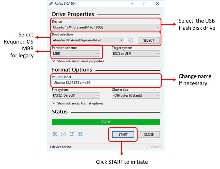
  2. Download the Rufus utility program to create a bootable USB flash disk. Rufus can be downloaded here:

  3. Insert a USB flash disk in the workstation & launch Rufus

  4. Follow the Rufus settings & initiate the bootable USB flash disk creation process

14.2 Hardware Setup

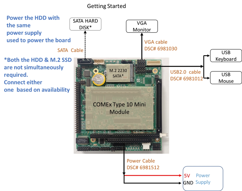
The illustration below shows the minimum hardware set up required to boot the system:

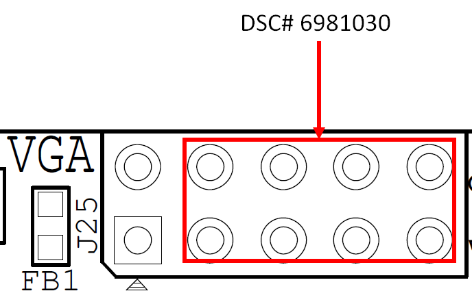
  1. Use the cable DSC# 6981012 at J5/J21 and connect a USB mouse & keyboard to the ports.

  2. Connect a SATA HDD at J26 or an M.2 M-Key 2230 sized SSD at J10. The system requires only 1 media to boot. Depending upon availability either one can be connected.

  3. Connect a 5V power supply at J11.

  4. Ensure all the connections are in tact.

  5. Double check the power supply.

  6. Power on system.

  7. On the initial boot, the system will prompt for installation settings. Set up as required.

  8. Once the OS installation is completed, the Desktop is loaded. The system is now ready to be used.

Use the cable DSC# 6981030 at J25 & connect a VGA monitor to the port. Make sure to leave out the pins 1& 2 to connect the cable as these pins are used to enable the system in headless mode (described in ). The VGA signals are available from the pin number 3. See illustration below:

Rufus
Section 8.9