22.2 Counter 1 – Counting, Totalizing, and Interrupt Functions
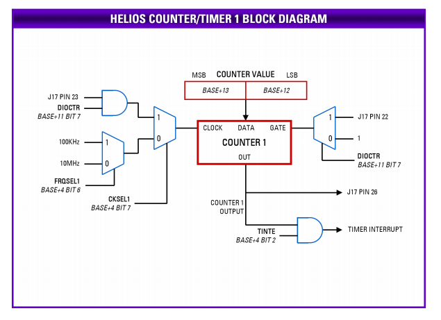
Counter 1 is similar to Counter 0 except that it is a 16-bit counter, and its clock, gate, and out connections have different options. The counter operates by counting down from the programmed divisor value. When the counter reaches a count of 1, it outputs a positive-going pulse equal to one input clock period. On the next input clock, the pulse terminates, and the counter reloads to the initial load value and repeats the process indefinitely as long as it is enabled. The output signal is available on I/O connector J17 pin 26.
When CKSEL1=0 in base+4, Counter 1 takes its input from the on-board clock source selected by FRQSEL1. When CKSEL1=1, counter 1 counts positive edges on data acquisition connector J17 pin 23, and DIOCTR in base+11 must also be set to 1 to configure this pin as an external clock input. This pin has a pull-up resistor, so the counter will not count if the pin is unconnected. For proper operation, the input signal must be no greater than 10MHz, with both high and low periods of the cycle a minimum of 50ns in duration.
When DIOCTR=1, the counter gate function is provided on pin 22 of the connector. If the gate is high, the counter counts, and if the gate is low, the counter holds its value and ignores input pulses. This pin has a pull-up resistor, so the counter can operate without any external gate signal attached. When DIOCTR=0, there is no gating, and the counter runs continuously when enabled.
Timer Interrupts
When TINTE=1 (base+4 bit 2), the output of timer 1 can be used to generate interrupts on the ISA bus at a userprogrammable rate. The interrupt occurs on the IRQ level selected with jumper block J21. When an interrupt occurs, status bit TINT=1 (base+7 bit 6). The interrupt routine must clear the interrupt by driving bit CLRT=1 (base+0 bit 2) before terminating. When an interrupt is pending, the IRQ line will be driven high. When no interrupt is pending, the board will release the IRQ line and it will be pulled low by the pull-down resistor configured with J21. It is possible for Helios to generate interrupts from up to 3 sources simultaneously. Thus clearing one interrupt will not necessarily cause the IRQ line to go low. It will only go low when all 3 circuits are inactive or have no interrupts pending.
Last updated