7.3 RS-422/RS-485 Configuration (J25, J26)
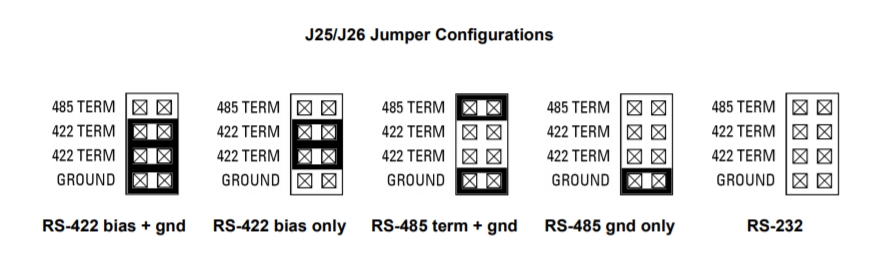
Use J25 to select the COM1 RS-422/RS-485 termination and J26 to select the COM2 RS-422/RS-485 termination. Any port configured for RS-232 should not have any jumpers installed. COM3 and COM4 are fixed RS-232, so no termination configuration is available for them. Although the diagrams below show labels on the jumper blocks, there are no labels on the board. The orientation of the block in the diagrams matches the orientation of the jumper block when the board is rotated so that the PC/104 connector is on the lower edge (facing you).
For RS-422: Installing two jumpers in the 422 TERM positions as shown will connect a 120 ohm termination resistor across the RX + and – lines and will also connect 1K ohm bias resistors to the RX lines. The + line is biased toward ground, and the – line is biased toward +5V. This sets the receiver to an inactive state when the receiver is unconnected. Both jumpers should be installed if termination / biasing is desired. Installing only one jumper will create unpredictable behavior by the receiver.
For RS-485: Installing a jumper in the 485 TERM position will connect a 120 ohm resistor across the differential driver/receiver pair. The RS-485 network should have a termination resistor installed at each end of the circuit but not at intermediate nodes.
For both RS-422 and RS-485: Installing a jumper in the GROUND position will provide a second signal ground on the 5th pin of each serial port’s 10-pin group on the serial port connector J8. This corresponds to pin 3 of a DB9 male connector when Diamond’s cable 6981166 is attached to connector J8. Each port already has a ground on pin 9 of the 10-pin group, corresponding to pin 5 on a DB9 male connector.
Label | Function |
485 TERM | RS-485 Tx termination resistor |
422 TERM | RS-422 Rx termination and bias resistors |
GROUND | 2 nd ground pin for RS-422 / RS-485 |
Last updated