8. CONNECTOR PINOUTS
This page describes the pinouts of various connectors available with the JETBOX-FLOYD system.
8.1 Input Power Connector
The system provides a barrel connector for main input power. The connector has a 2.5mm center pin and is intended for use with mating connectors with 2.5mm inner diameter and 5.5mm outer diameter. Input voltage = +7V to +24V.
The connections for the power input connector are Tip = +V and Ring = -V.
Connector Part Number: PJ-202BH
Front Panel Exposure: YES
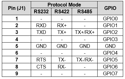
8.2 Serial Port 1 (SER 1)
JETBOX-FLOYD has two Serial Ports of which one of the serial ports, SER 1 has a dedicated connector terminated on J1. The serial port SER 1 is directly accessible on the front panel. The second serial port SER 2 is not directly exposed on the front panel; rather it is accessible on the front panel at EXP 1.
The SER 1 is multiplexed with DIOs with assembly options. The DIOs from the connector J9 on the Floyd carrier card can be routed to SER 1 (J1) connector. The pinouts of SER 1 connector are as shown below:
Connector Part Number: A-DS 09 A/KG-T2S
Front Panel Exposure: YES
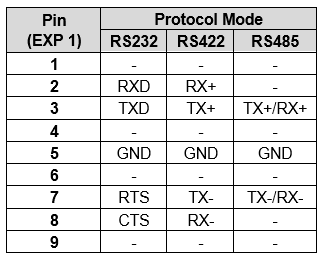
8.3 Serial Port 2 (EXP 2)
By default, the serial port 2 SER 2 is terminated at J9. To enhance the functionalities of the Jetbox-Floyd, the SER 2 is made available on the front panel at EXP 2. The pinouts of the SER 2 at EXP 2 are as shown below:
Connector Part Number: 010309-00002201
Front Panel Exposure: YES, on EXP 1
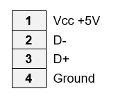
8.4 USB2 Ports 1,2
The Jetbox-Floyd hosts two USB 2.0 ports accessible on a vertically stacked standard USB 2.0 Type A socket that uses standard pinout. The pinouts are as shown below:
Connector Part Number: UB1112C-8FDH-4F
Front Panel Exposure: YES
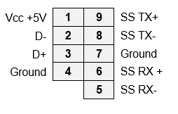
8.5 USB3 Port
The Jetbox-Floyd hosts one USB 3.0 port accessed via an upright standard USB 3.0 receptacle. The pinouts of the connector are as shown below:
Connector Part Number: UEA3119C-4EB1-4H
Front Panel Exposure: YES
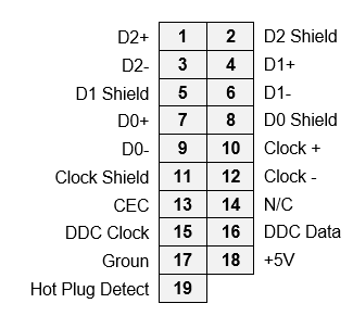
8.6 HDMI Ports 1 & 2
Two HDMI ports are available on a dual-port vertical stacked standard connector. The connector follows the standard HDMI pinout.
Audio output is supported only in the HDMI - 1 (upper port).
The HDMI - 2 (lower port) is available on the JB-FLD-***-01 models only.
The pinouts are as follows:
Connector Type/ Part Number: QJ11191-DFB1-4F-AX3
Front Panel Exposure: YES
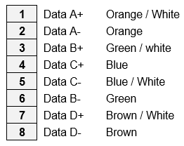
8.7 Ethernet Ports 1 & 2
The Ethernet ports are terminated on a standard dual port PoE+ and RJ45 connector that has built-in magnetics and LEDs. The connector follows standard TIA/EIA 568B pinout. The ETHERNET - 2 (lower port) is available on the JB-FLD-***-01 models only.
The pinouts are as follows:
Connector Part Number/Type: LPJG17098-8AENL
Front Panel Exposure: YES
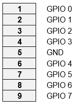
8.8 Digital I/Os (EXP 2)
The DIOs & the SER 2 on the Floyd carrier board of the Jetbox-Floyd are terminated on the same connector J9. This connector is accessed with a cable and exposed on the front panel. The SER 2 from J9 is terminated at EXP 1 on the front panel & the DIOs from J9 are terminated at EXP 2.
The DIO pinouts terminated at EXP 2 are as shown below:
Connector Part Number/Type: 2x10, 2.54 mm Header
Front Panel Exposure: YES, on EXP 2
8.9 Reset Switch
The Reset switch is used to reset the Jetbox-Floyd system. When the Reset switch is pressed, the system goes into Reset mode until the switch is released. When the switch is released, the system comes out of Reset mode & system boots to the operating system.
8.10 Recovery Switch
The Recovery switch is used to operate the system in Recovery mode. The recovery mode is used by the system to update its Board Support Package (BSP).
The usage of the Recovery switch has been detailed in Section 14. REPORGRAMMING THE EMBEDDED LINUX IMAGE.
8.11 SMA Antenna Connectors 1, 2
Jetbox-Floyd system provides 2 SMA connectors to connect external antennas. These connectors can be used when a WiFi or LTE module is used to extend the connectivity on the M.2 or mPCIe expansion.
The WiFi/LTE modules can be wired to the SMA connector internally with U.F.L to SMA cables.
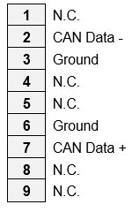
8.12 EXP 2: Controller Area Network (CAN) (Optional)
The CAN interface is optionally accessible from the front panel. The pinouts of the EXP 2 for CAN interface are as shown below:
Connector Part Number/Type: 010309-00002201
Front Panel Exposure: NO, optionally available on EXP 2
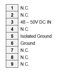
8.13 EXP 1: PoE Power Input (Optional)
The PoE Power Input connector is optionally accessible from the front panel. The pinouts of the EXP 2 for PoE Power Input are as shown below:
Connector Part Number/Type: 010309-00002201
Front Panel Exposure: NO, optionally available on EXP 2
NOTE: The subsequent connectors have been referenced with the reference designators on the Floyd base board. Refer Floyd User Manual for more details.
8.14 J19: PCIe M.2 SSD Socket (M-Key, 2280 Size)
The Floyd carrier board is equipped with an M.2 PCIe SSD M-keyed connector for 2280 sized modules for storage applications.
The PCIe link routing from the Jetson module to the M.2 socket varies according to the Jetbox-Floyd model.
JB-FLD-NAO/XNX-01: The PCIe x4 link from the Jetson module is routed to a switch which provies 3 PCIe x1 links for the M.2 socket, PCIe minicard socket, and 2nd Ethernet port.
JB-FLD-NAO/XNX-02The x4 PCIe link is directly connected to the M.2 socket for maximum bandwidth. The minicard and 2nd Ethernet port are not present. With the Jetson Xavier NX module installed, an additional PCIe x1 lane interface can be mapped from the NX to the second Ethernet.
NOTE: Contact Diamond Systems Corp for custom build options.
The M.2 socket follows standard pinouts & the pinouts of the connector J19 are as shown below:
Ground | 1 | 2 | 3.3V |
Ground | 3 | 4 | 3.3V |
PETn3 | 5 | 6 | N/C |
PETp3 | 7 | 8 | N/C |
Ground | 9 | 10 | LED1# |
PERn3 | 11 | 12 | 3.3V |
PERp3 | 13 | 14 | 3.3V |
Ground | 15 | 16 | 3.3V |
PETn2 | 17 | 18 | 3.3V |
PETp2 | 19 | 20 | N/C |
Ground | 21 | 22 | N/C |
PERn2 | 23 | 24 | N/C |
PERp2 | 25 | 26 | N/C |
Ground | 27 | 28 | N/C |
PETn1 | 29 | 30 | N/C |
PETp1 | 31 | 32 | N/C |
Ground | 33 | 34 | N/C |
PERn1 | 35 | 36 | N/C |
PERp1 | 37 | 38 | N/C |
Ground | 39 | 40 | N/C |
PETn0 | 41 | 42 | N/C |
PETp0 | 43 | 44 | N/C |
Ground | 45 | 46 | N/C |
PERn0 | 47 | 48 | N/C |
PERp0 | 49 | 50 | PERST# |
Ground | 51 | 52 | CLKREQ# |
REFCLKN | 53 | 54 | PEWake# |
REFCLKP | 55 | 56 | N/C |
Ground | 57 | 58 | N/C |
KEY | |||
N/C | 67 | 68 | SUSCLK |
PEDET | 69 | 70 | 3.3V |
Ground | 71 | 72 | 3.3V |
Ground | 73 | 74 | 3.3V |
Ground | 75 |
Connector Part Number/Type: 10128798-001RLF
Connector Key: M-Key
Add-on Module: M.2 2280 SSD (W 22 mm x L 80 mm)
Front Panel Exposure: NO, accessed by opening the TOP heat spreader plate
8.15 J17: Minicard Socket
The TX (Transmit) and RX (Receive) signals are transmitted by the host. The RX signal on the socket is driven by the TX signal on the installed module and vice versa. The two mounting standoffs at the far end of the Minicard Module installation site are not connected to Ground.
The pinouts for the PCIe Mini Card connector are as shown below:
1 | 2 | +3.3V | |
3 | 4 | Ground | |
5 | 6 | +1.5V | |
Clockreq- | 7 | 8 | |
Ground | 9 | 10 | |
PCIe 1 Clk- | 11 | 12 | |
PCIe 1 Clk+ | 13 | 14 | |
Ground | 15 | 16 | |
KEY | KEY | ||
17 | 18 | Ground | |
19 | 20 | Disable- | |
Ground | 21 | 22 | PCIe Reset- |
PCIe 1 RX- | 23 | 24 | +3.3V |
PCIe 1 RX+ | 25 | 26 | Ground |
Ground | 27 | 28 | +1.5V |
Ground | 29 | 30 | SMB Clock |
PCIe 1 TX- | 31 | 32 | SMB Data |
PCIe 1 TX+ | 33 | 34 | Ground |
Ground | 35 | 36 | |
Ground | 37 | 38 | |
+3.3V | 39 | 40 | Ground |
+3.3V | 41 | 42 | WWAN LED- |
Ground | 43 | 44 | WLAN LED- |
45 | 46 | WPAN LED- | |
47 | 48 | +1.5V | |
Pull-up to +3.3V | 49 | 50 | Ground |
51 | 52 | +3.3V |
Connector Part Number/Type: MM60-52B1-E1-R650
Front Panel Exposure: NO, accessed by opening the TOP heat sink plate
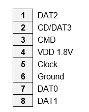
8.16 J18:Micro SD Connector
The Floyd carrier board provides a standard Micro SD connector as an additional storage option.
The pinouts of the connector are as shown below:
Connector Part Number: 114-00841-68
Front Panel Exposure: NO, accessed by opening the TOP heat spreader plate
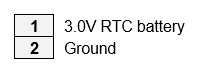
8.17 J15: RTC Battery Connector
The RTC battery connector is used to supply voltage for RTC.
The pinouts for the RTC Battery connector are as shown below:
Connector Part Number: 0022035025
Front Panel Exposure: NO, accessed by opening the TOP heat spreader plate
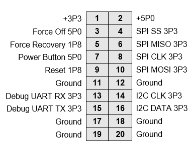
8.18 J16: Utility Connector
The carrier board provides access to utility signals on a 2x10 header.
The pinouts for the utility connector are as shown below:
Connector Part Number: 220-97-36GB01
Connector Type: Connector: 2x10, 2 mm Header
Front Panel Exposure: NO, accessed by opening the TOP heat spreader plate
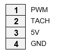
8.19 J20: Fan Connector
Fan is not used with Jetbox-Floyd but with Floyd carrier board only when used as a standalone unit. The thermal solution for Jetbox-Floyd is integrated into the system.
The pinouts for the fan connector are specified below:
Connector Part Number: 0533980471-2
Supported Fan Model: Delta ASB0305HP-00CP4
Front Panel Exposure: NO, accessed by opening the TOP heat spreader plate
8.20 J12, J13, J14: Camera Connectors
The camera interface is accessible when the Floyd carrier board is used as a standalone unit & not with Jetbox-Floyd system.
The carrier board embeds three identical 30-pin connectors for multiple CSI Camera connectivity. The 30-pin Micro Coaxial connectors are used to connect camera modules on the carrier board.
The pinouts for the CSI connectors are as shown below:
J12 | J13 | J14 | |||||
1 | V_3P3 | 1 | V_3P3 | 1 | V_3P3 | ||
2 | V_3P3 | 2 | V_3P3 | 2 | V_3P3 | ||
3 | V_1P8_CAM | 3 | V_1P8_CAM | 3 | V_1P8_CAM | ||
4 | Ground | 4 | Ground | 4 | Ground | ||
5 | Ground | 5 | Ground | 5 | Ground | ||
6 | CAM2_PWDN_1P8_E | 6 | CAM1_PWDN_1P8_E | 6 | CAM0_PWDN_1P8_E | ||
7 | CAM2_I2C_SCL_1P8_E | 7 | CAM1_I2C_SCL_1P8_E | 7 | CAM0_I2C_SCL_1P8_E | ||
8 | CAM2_I2C_SDA_1P8_E | 8 | CAM1_I2C_SDA_1P8_E | 8 | CAM0_I2C_SDA_1P8_E | ||
9 | Ground | 9 | Ground | 9 | Ground | ||
10 | CSI2_D2_N | 10 | CSI1_D2_N | 10 | CSI0_D2_N | ||
11 | CSI2_D2_P | 11 | CSI1_D2_P | 11 | CSI0_D2_P | ||
12 | TRIG_CSI_CAM_2_R_E | 12 | TRIG_CSI_CAM_1_R_E | 12 | TRIG_CSI_CAM_0_E | ||
13 | SPI1_CLK_E | 13 | SPI1_CLK_E | 13 | SPI1_CLK_E | ||
14 | Ground | 14 | Ground | 14 | Ground | ||
15 | CSI2_D1_N | 15 | CSI1_D1_N | 15 | CSI0_D1_N | ||
16 | CSI2_D1_P | 16 | CSI1_D1_P | 16 | CSI0_D1_P | ||
17 | Ground | 17 | Ground | 17 | Ground | ||
18 | Ground | 18 | Ground | 18 | Ground | ||
19 | CSI2_D0_N | 19 | CSI1_D0_N | 19 | CSI0_D0_N | ||
20 | CSI2_D0_P | 20 | CSI1_D0_P | 20 | CSI0_D0_P | ||
21 | NRST_CSI_CAM_2_E | 21 | NRST_CSI_CAM_1_E | 21 | NRST_CSI_CAM_0_E | ||
22 | Ground | 22 | Ground | 22 | Ground | ||
23 | SPI1_SS2_E# | 23 | SPI1_SS1_E# | 23 | SPI1_SS0_E# | ||
24 | CSI2_CLK_N | 24 | CSI1_CLK_N | 24 | CSI0_CLK_N | ||
25 | CSI2_CLK_P | 25 | CSI1_CLK_P | 25 | CSI0_CLK_P | ||
26 | Ground | 26 | Ground | 26 | Ground | ||
27 | CSI2_D3_N | 27 | CSI1_D3_N | 27 | CSI0_D3_N | ||
28 | CSI2_D3_P | 28 | CSI1_D3_P | 28 | CSI0_D3_P | ||
29 | FLASH_CAM_2_E | 29 | FLASH_CAM_1_E | 29 | FLASH_CAM_0_E | ||
30 | SPI1_MOSI_E | 30 | SPI1_MOSI_E | 30 | SPI1_MOSI_E |
Connector Part Number: 20682-030E-02
Mating Cable Part Number: Compatible cables are generally included with the camera kit
Compatible Cameras:
Vendor Model number Description
Econ e-CAM55_CUMI0521_MOD 5MP normal light fixed focus
Econ e-CAM21_CUMI290_MOD 2MP ultra-low-light fixed focus
Econ e-CAM137A_CUMI1335_MOD 13MP normal light fixed focus
Front Panel Exposure: NO, accessed by opening the TOP heat spreader plate
Last updated