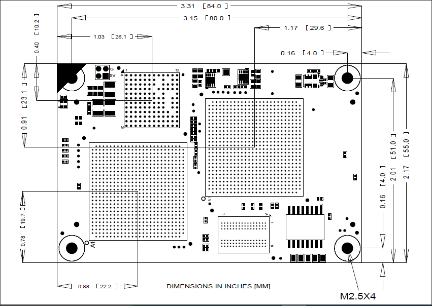
8. Mechanical Drawing
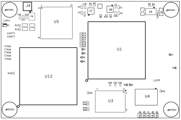
1.1 Component Placement
The figures below show the locations of key components and I/O connectors.
The main board has a High-speed connector on the bottom side for mating with the optional daughter-board. The daughter-board contains a mating connector on its top side. The two boards are mated back to back so that the heat generating components and heat sinks are on Main board top side the outer sides of both boards when mated together.
Board Dimensions
3D model of board is available.
Last updated